Core Trades
Core trades such as plumbing, electrical, HVAC, and concrete work are the foundation of construction, making up approximately 30% of the exam content. This chapter will guide you through the essential knowledge and practices within these key areas, covering everything from water supply systems and electrical calculations to HVAC installation and concrete pouring. You'll also learn about earthwork and surveying, insulation, acoustical considerations, and weatherproofing techniques. Mastery of these core trades is vital for ensuring the structural integrity, safety, and comfort of any building project, equipping you with the skills necessary to execute these tasks effectively and in compliance with California’s rigorous building codes.
Plumbing
General Requirements for water supply
All plumbing fixtures must be furnished with a sufficient flow of potable water, in a manner that meets approval. Pipes carrying potable water should be distinguished by a colored pipe or band that features a green background with white letters. Pipes carrying non-potable water should be marked with a yellow background and black, uppercase letters stating, “CAUTION: NONPOTABLE WATER, DO NOT DRINK.” These markings should be visible every 20 feet, or at least once in each room.
Water Supply Pipe Sizing
The diameter of water supply pipes to any structure should be no less than 3/4 inches. Nonetheless, many residential buildings will necessitate a supply pipe of one inch or larger. The sizing of water supply pipes is contingent on the water supply demand of a building. Utilize the below table to ascertain the number of fixture units and the smallest acceptable size of branch pipes in a building.
Sizing fixture unit

Backflow Prevention Devices
To prevent pollution or cross-connection hazards, each plumbing fixture or structure should have a suitable backflow prevention device installed. Commonly used backflow prevention systems are air gaps, atmospheric vacuum breakers (AVB), double check valves, and barometric loops.
Water Supply Valves
Valves up to 2 inches must be of the brass type, while valves over 2 inches can have cast iron or brass bodies. Each gate or ball valve should be a full-way type, with non-corrosive internal parts. A full-bore valve, with an opening as large as the pipe it serves, should be installed in all buildings, enabling water shut-offs for the entire building. Also, a full-bore valve should be fitted on the cold water inlet of water heaters. At each connection from an appliance to the water supply system, a shut-off valve should be installed.
Pressure Regulators/Relief Valves
If the water pressure from the main or other source does not provide at least 15 psi after considering friction and other pressure losses, then a tank and pump should be installed to compensate, ensuring the required 15 psi of pressure. A pressure relief regulator needs to be installed whenever water pressure exceeds 80 psi. Pressure relief valves must be automatic with a drain, and each relief valve must be set to a maximum pressure of 150 psi or less. Pressure regulators need to be installed above the ground and be safe from freezing or other weather conditions. The pressure regulator should have an accessible strainer, although not always mandatory.
Testing Water Supply Systems
After a section of the hot and cold water supply system has been successfully installed, the water supply system should be tested and proven to be tight under working water pressure. The water used in the tests must come from a potable supply source. Excluding plastic piping, a 50 psi air pressure test should be carried out. In both tests, the piping must withstand the test without leaking for at least 15 minutes.
Sanitary Drainage
Every water fixture generates waste that needs to be gathered into the sanitary piping system. PVC is most commonly used in sanitary piping. Drainage piping can be made from cast iron, galvanized steel, galvanized malleable iron, copper, brass, or stainless steel 304 or 316L, Schedule 40 ABS DWV, Schedule 40 PVC DWV, or extra-strength vitrified clay pipe, or other approved materials with a smooth and uniform bore. However, there are exceptions:
- Galvanized wrought iron, stainless steel 304, or galvanized steel pipe should not be used underground and must be kept at least six inches above ground.
- ABS and PVC DWV installations are restricted to residential construction no more than two stories high.
- Vitrified clay pipes or fittings can't be used above ground or when pressurized by a pump or ejector, and must be kept at least 12 inches under the ground.
- Stainless steel 304 pipe and fittings should not be installed underground and must be kept at least 6 inches above ground.
Drainage pipes should have a slope of at least 1/4 inch per foot. If a slope of 1/4 inch per foot is not achievable, a larger size pipe of at least 4 inches can be used with a slope of 1/8 inch per foot.
Sizing Drainage
To size drainage piping, determine the number of fixture units using the below table and compare it to the minimum trap and trap arm sizes.
Piping size table 1
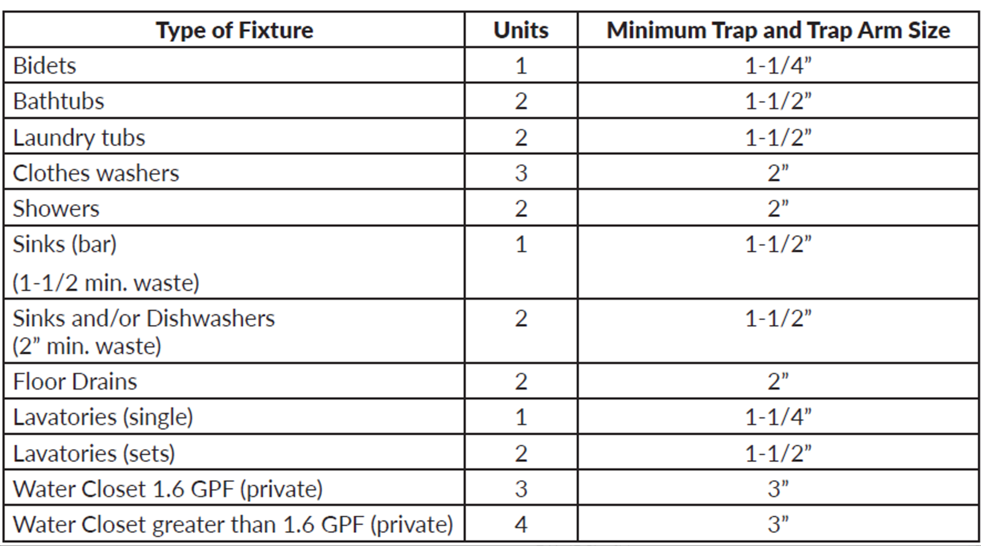
To determine the appropriate sizing of the drainage pipe that needs to horizontally support 1 bathtub, 2 water closets, and 2 sinks, we first refer to the above table. We see the total fixture units required is 12. With this information, we then consult the below table to find the correct size for the drainage pipe.
Piping size table 2
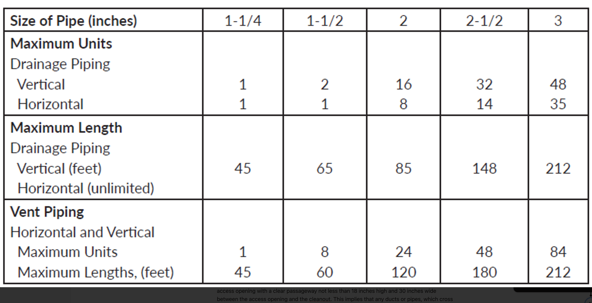
As can be seen, 12 units will require a drainage pipe to be 2-1/2 inches in size. In this example, a 2-1/2-inch horizontal pipe can support up to 14 total fixture units.
Cleanouts
There should be a cleanout at the higher end of each drainage pipe with the following exclusions:
- Horizontal branches less than 5 feet long, unless connected to sinks or urinals.
- Pipes which slope 18 degrees or more from the horizontal.
- Pipes used above the first story.
An accessible cleanout should be used for every 100 feet and for every combined change of direction exceeding 135 degrees. The underfloor cleanouts should be within 20 feet of the access opening with a clear passageway not less than 18 inches high and 30 inches wide between the access opening and the cleanout. This implies that any ducts or pipes, which cross this pathway, should have 18 inches of clear space below them. There should be 12 inches of clear space in front of a 2 inch or less cleanout, and 18 inches for those greater than 2 inches. Cleanouts for underground pipes should be extended to grade.
Traps and Venting
Traps must be installed as close as possible to a fixture outlet with a maximum distance of 24 inches from the outlet to the trap. Traps can serve up to three compartment sinks or lavatories. Care must be taken with venting, since it is commonly placed near the trap. Backpressure and siphonage protection must be assured. When the trap arms must change direction, it must be done with turn changes less than 90 degrees vertically. Traps shall be self-cleaning with a minimum liquid seal of 2 inches and a maximum seal of 4 inches.
The most common material used for venting is PVC, but copper can also be used. The size of the venting system depends on the number of drain fixture units traveling across the length of any sanitary branch. The minimum size of a venting pipe is 1-1/4-inches in diameter, and should not be less than half the diameter of the connected sanitary pipe. The below table lists the minimum trap, and horizontal and vertical pipe sizes.
Minimum trap, horizontal and vertical pipe size table

Vent Pipe Slope and Connections
Vents shall rise at least 6 inches from a horizontal drainage pipe before making any turns. If this condition can’t be met then drainage, fittings, or a grade in the horizontal vent pipe must be granted to ensure that no waste is going to travel up the vent. Wherever a vent pipe joins a horizontal drainage pipe, it should be joined to the upper half of the pipe. A vent joined to the side of a horizontal drainage pipe is not permitted. Vent pipes may not be installed horizontally, with less than 45 degree slope, unless there are no less than 6 inches over the flood level height of the served fixture. The connection of the vent pipe to the drainage pipe should be above the height of the standing water in the trap, excluding toilets.
Vents must extend above the roof at least 6 inches and keep a distance of 1 foot from any vertical surface. In addition, roof vent pipes must be kept at least 10 feet horizontally or 3 feet vertically from any window, door, or air intake to the building.
Gas Piping
Gas piping depends upon the maximum demand possible for the dwelling and the minimum pressure that any appliance or inlet requires in order to work properly. Those numbers are based on the appliance manufacturer’s Btu/h demand information. Gas piping consists of metallic and commonly found plastic materials. The difference between water and gas piping is that gas piping is that gas piping requires complete part replacement since repairs are not feasible.
Gas Piping Installation
Underground piping must be installed with a minimum of 18 inches of cover or 12 inches of cover if external damage is not probable. Piping through foundations is allowed, however, a protective sleeve must be installed. Internal piping must be fixed and protected from damage. If the piping passes through an exterior wall, it must have corrosion protection. Gas piping is installed both vertically and horizontally, with a maximum slope of 1/4 inch for every 15 feet horizontal feet. The piping support spacing is shown in the support pipping table below.
As evident, a drainage pipe of 2-1/2 inches is required for 12 units. To illustrate, a horizontal pipe of 2-1/2 inches can accommodate up to 14 total fixture units.
Cleanouts
Each drainage pipe should have a cleanout at its higher end, excluding the following situations:
- Horizontal branches shorter than 5 feet, unless they are connected to urinals or sinks.
- Pipes that have a slope of more than 18 degrees from the horizontal.
- Pipes used above the first story.
A cleanout that can be accessed easily should be present for every 100 feet and for every combined direction change exceeding 135 degrees. The cleanouts under the floor should be no more than 20 feet from the access opening and a clear pathway of at least 18 inches high and 30 inches wide should be maintained between the access opening and the cleanout. This means any pipes or ducts crossing this pathway should maintain 18 inches of clear space beneath them. There should be a clear space of 12 inches in front of a cleanout of 2 inches or less, and 18 inches for those larger than 2 inches. Cleanouts for pipes underground should be extended to the grade level.
Traps and Venting
Traps should be located as near as possible to a fixture outlet, with a maximum distance of 24 inches from the outlet to the trap. Traps can serve up to three compartment sinks or lavatories. Special care must be taken with venting, as it is typically located near the trap. Backpressure and siphonage protection must be provided. When the trap arms need to change direction, it should be done with turn changes of less than 90 degrees vertically. Traps should be self-cleaning with a minimum liquid seal of 2 inches and a maximum seal of 4 inches.
PVC is the most common material used for venting, but copper can also be used. The size of the venting system depends on the number of drain fixture units that move across any sanitary branch. The venting pipe should be at least 1-1/4-inches in diameter and no less than half the diameter of the connected sanitary pipe. The above table lists the minimum trap, and horizontal and vertical pipe sizes.
Vent Pipe Slope and Connections
Vents should rise at least 6 inches from a horizontal drainage pipe before making any turns. If this is not possible, then drainage, fittings, or a grade in the horizontal vent pipe must be provided to ensure that waste does not travel up the vent. Whenever a vent pipe connects to a horizontal drainage pipe, it should be connected to the upper half of the pipe. A vent connected to the side of a horizontal drainage pipe is not allowed. Vent pipes should not be installed horizontally, with a slope of less than 45 degrees, unless they are at least 6 inches above the flood level height of the served fixture. The connection of the vent pipe to the drainage pipe should be above the height of standing water in the trap, excluding toilets.
Vents must extend at least 6 inches above the roof and maintain a distance of 1 foot from any vertical surface. Also, roof vent pipes should be at least 10 feet horizontally or 3 feet vertically away from any window, door, or air intake to the building.
Gas Piping
Gas piping relies on the maximum possible demand for the dwelling and the minimum pressure that any inlet or appliance needs to function properly. These numbers are based on the appliance manufacturer’s Btu/h demand information. Gas piping is made up of metallic and commonly found plastic materials. The difference between water and gas piping is that gas piping requires complete part replacement since repairs are not feasible.
Gas Piping Installation
Underground piping must be installed with a minimum cover of 18 inches or a cover of 12 inches if external damage is unlikely. Piping through foundations is allowed, however, a protective sleeve should be installed. Internal piping must be secure and protected from damage. If the piping passes through an exterior wall, it must be protected against corrosion. Gas piping is installed both vertically and horizontally, with a maximum slope of 1/4 inch for every 15 feet horizontal feet. The spacing for piping support is shown in the below table.
Support of piping table

The upper limit for gas piping system pressure in buildings is 5 psi, with the exception of situations where the system is welded and the enclosed piping is safeguarded against gas build-up. To ensure accessibility, gas outlets should be positioned in a way that they are not hidden behind doors, should possess a minimum unthreaded portion of 1 inch, and should be at least 2 inches away from the floor.
Plumbing
In this section, we will discuss the standard requirements and practices for plumbing in the State of California. This includes the supply of potable water and waste, ventilation of water supply systems, gas supply, and special requirements for common plumbing appliances such as water heaters.
Water Properties
- Boiling Temperature: 212°F at atmospheric pressure
- Freezing Temperature: 32°F at atmospheric pressure
- Density: 62.4 lb/ft³ or 8.34 lb/gallon
- Pressure per 3.3 feet of water column: 9.8 kPa / 0.1 bar / 1.4 psi
- Volume Equivalences: 1 cubic foot / 1,728 cubic inches / 7.48 gallons / 957 ounces
Pipe Supports
- Cast Iron
- Horizontal Support: Every alternate joint, unless over 4 feet, then support each joint
- Vertical Support: Base and every floor, not exceeding 15 feet
- Copper & Copper Alloys
- Horizontal Support: 1-½ inches and smaller, every 6 feet; 2 inches and larger, every 10 feet
- Vertical Support: Every floor, not exceeding 10 feet
- Steel Pipe for Water or DWV
- Horizontal Support: ¾ inch and smaller, every 10 feet; 1 inch and larger, every 12 feet
- Vertical Support: Every alternate floor, not exceeding 25 feet
- Schedule 40 PVC & ABS DWV
- Horizontal Support: All sizes, every 4 feet; expansion allowance every 30 feet
- Vertical Support: Base and every floor
- CPVC, PEX, PP
- Horizontal Support: 1 inch and smaller, every 3 feet; 1-¼ inches and larger, every 4 feet
- Vertical Support: Base and every floor
Copper pipes should not come into direct contact with supports, and any metal support that makes direct contact with a copper water pipe could potentially cause noise when the water flow is turned on or off at the fixtures. Moreover, gas piping needs more support compared to water pipes.
Underground pipes should always have support prior to backfilling. In rocky soil, where it is not possible to achieve a flat trough bottom, sand must be used to create a level bed for correct pipe installation. Underground water pipes should have a minimum burial depth of 12 inches.
Plumbing Fixtures
The positioning of water closets necessitates a minimum of 15 inches on center from any side wall and at least 30 inches on center from any other similar fixture, as demonstrated in the figure below. A minimum clearance of 24 inches in front of all fixtures is required. Shower designs should incorporate a finished dam, curb or threshold that is no less than an inch below the back and sides. This finished dam or threshold should exceed 2 inches in depth, but not exceed 9 inches when measured from the dam's top to the drain's top. The finished shower floor should possess a slope ranging between 1/4 to 1/2 inch per foot.
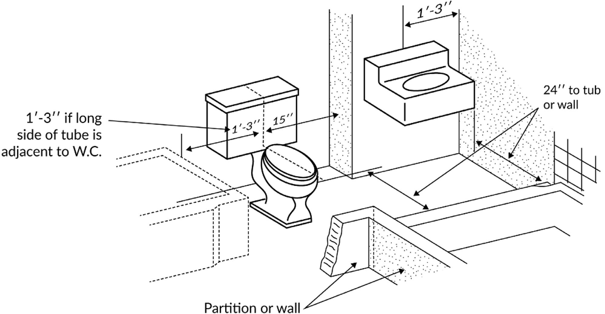
Plumbing fixture layout
Testing DWV Systems
To test drainage waste venting (DWV) systems, either water or air can be used. The water test is conducted by closing all system openings and filling it with water until it reaches a level at least 10 feet above the highest fitting. An air test of 5 psi is another option, but it should be conducted with a gauge that has a maximum full scale rating of 10 psi.
Water Heaters
Water heaters in residential environments are frequently placed in garages. Appliances that use gas must be installed with the burners and ignition devices at least 18 inches above the ground. Water heaters situated in garages must be positioned or shielded in a way that prevents damage from a moving vehicle. Water heaters must be installed or repaired with the approval of the local jurisdiction and must have a minimum capacity based on the number of bathrooms and bedrooms in the house. Refer to the below table for the first hour ratings.
First hour rating table

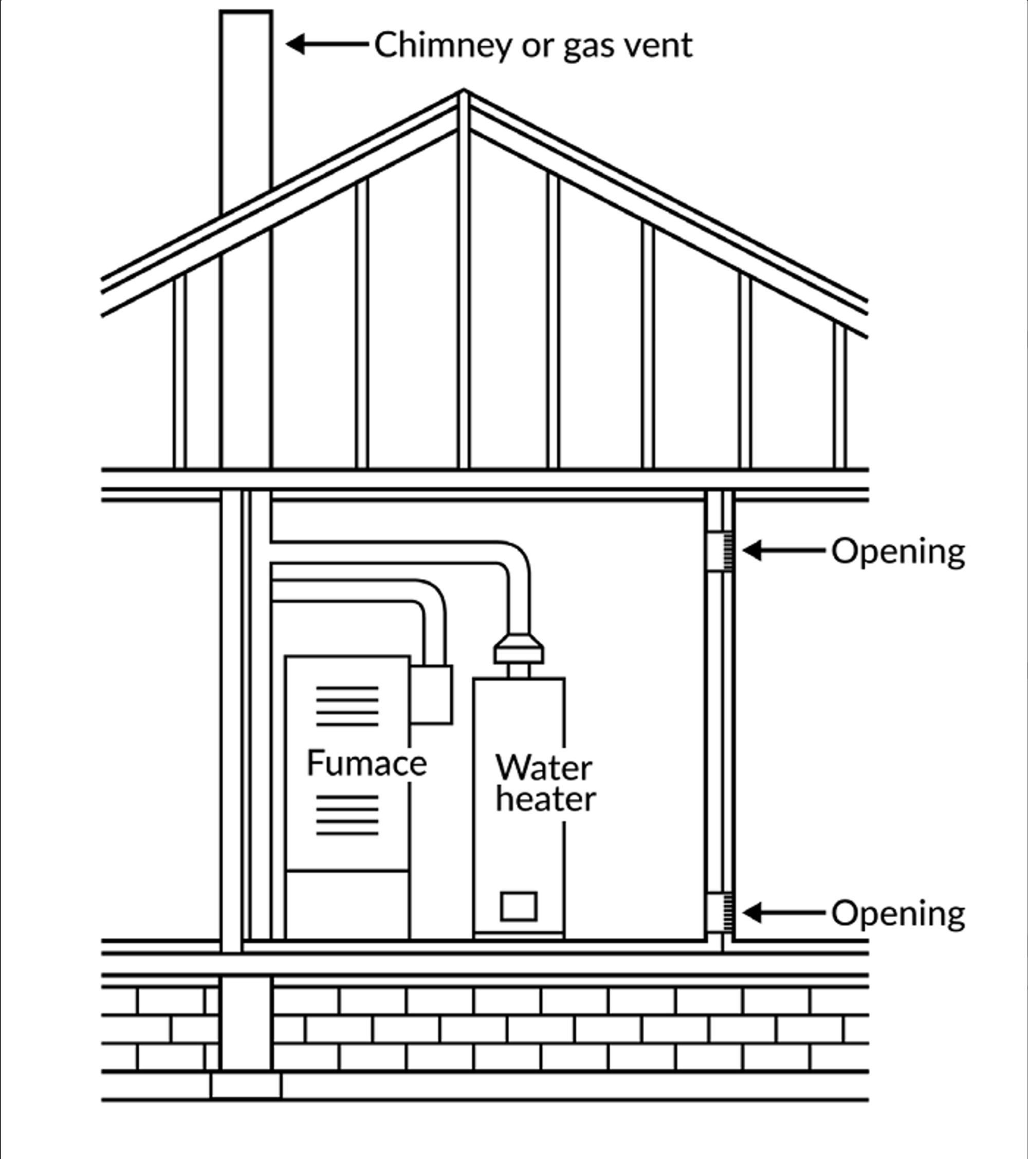
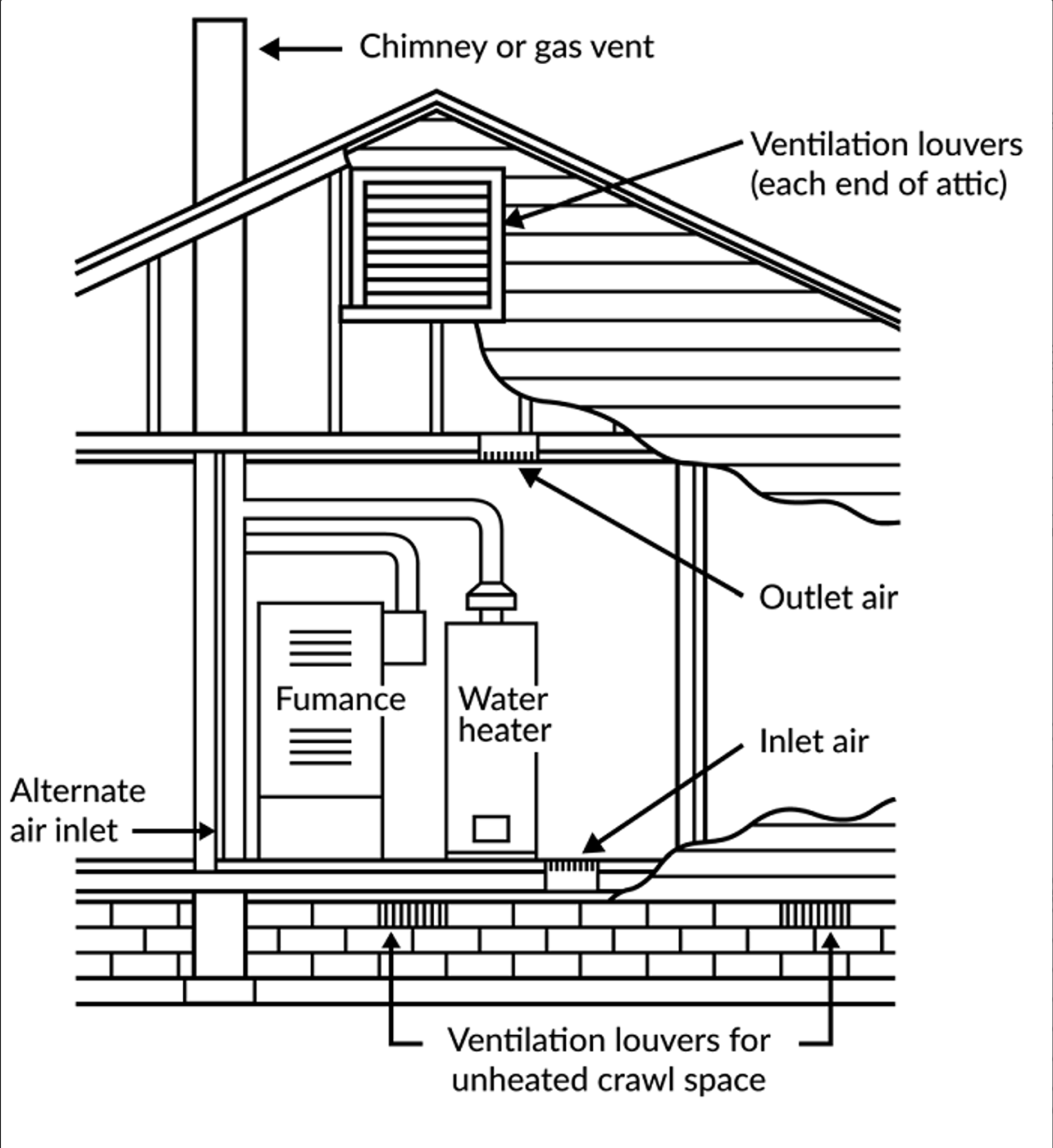
All water heaters must be equipped with devices that limit pressure and temperature. The rooms where water heaters are positioned must provide a minimum of 50 cubic feet of air per Btu/h for combustion. It's not permissible to install a shutoff valve between the water heater and the relief valve, or on any of the discharge pipes. On devices like these, the device's rated steam relief capacity or the hourly Btu discharge capacity must not fall short of the water heater's input rating.
All combustion air from adjacent indoor spaces through indoor combustion air opening
Combustion air from outdoors inlet air from ventilated crawl space outlet air to ventilate attic
Seismic Protection
In the state of California, it is of utmost importance to safeguard all new and replacement water heaters against seismic damage. The measures that must be taken are as follows:
- The water heater must be fastened in the top third and bottom third of its vertical dimensions. Lower strapping should maintain a minimum clearance of 4 inches from the controls.
- If the water heater is grounded, it must have a minimum of 3 inches of suitable base material for support.
Electrical
Electrical Calculations
The electrical portion of the exam requires the execution of basic electrical calculations. Many of these calculations are based on Ohm’s Law. The following electrical symbols and abbreviations are frequently used:
I - denotes current and is measured in Amperes (A)
V, E - stand for voltage and is measured in Volts (V)
R - signifies resistance and is measured in Ohms (Ω)
P, W - represent power and is measured in Watts (W)
Whenever there is an electrical current passing through a conductor, three elements are always present:
- The potential difference across the conductor, measured in Volts (V), which is responsible for the flow of the current.
- The resistance (R) of the conductor, measured in ohms (?), which the current has to overcome.
- The current strength (I), measured in Amperes (A), is maintained in the conductor as it overcomes the resistance.
The diagrams represented in Figure 43(a) and 43(b) illustrate a formula. To use these diagrams as a formula, cover the end variable you are interested in. If the top variable on the pyramid is covered, multiply the two bottom variables. However, if any of the bottom variables are covered, divide the top variable by the remaining bottom variable.
EXAMPLE: If you are attempting to put 1500 watts on 120 V circuit, how many amps are utilized?
First, decide which pyramid (formula) should be used. By examining the question, determine which values are given and which values are sought. In this example, the values for P (watts), E (volts), and I (amps) are being used. Therefore, the left pyramid (formula) will be used. Cover “I” (amps) and divide “P” (watts) by “E” (volts).
1500 Watts ÷ 120 Volts = 12.5 Amps
Conductor Sizing
Conductors are sized according to a standard wire gauge system known as the American wire gauge (AWG) scale, which ranges from 18 AWG to 4/0 AWG. Larger conductors are sized in 1,000 circular mils (MCM) or Kcmil units, and can range from 250 to 2,000 Kcmil, as shown in the image below.
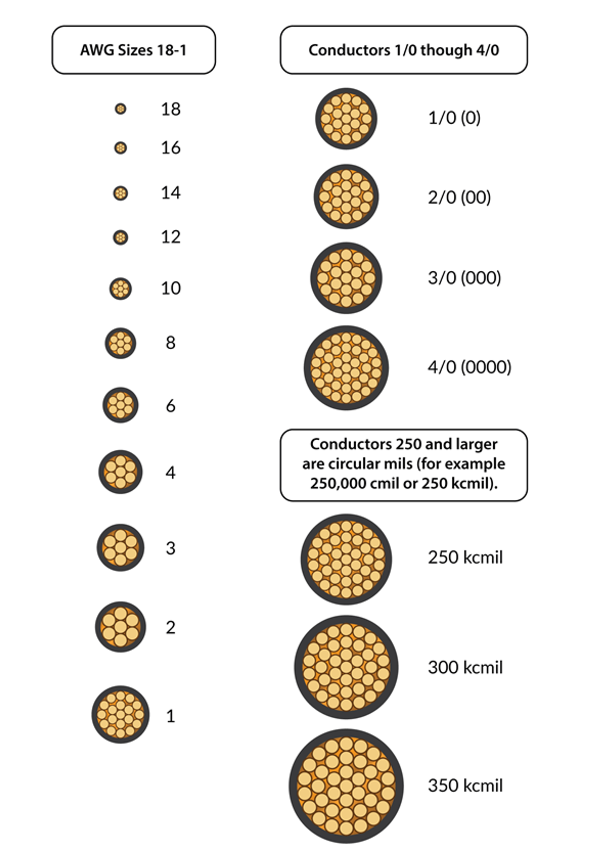
Conductor Sizes – AWG or Kcmil
Cable Types
In residential electrical projects, professionals often use "cable" as opposed to individual conductors. The term "cable" refers to a unit that consists of two or more conductors encased or sheathed together. The market offers a variety of cable types, including: single-conductor, nonmetallic cable (NM) like Romex® brand NM cable, metal clad (MC), and underground feeder (UF).
Single Conductor Cable
One of the most frequently used single conductor cables in the field is the THHN or THWN-2 (refer to the below image). Each letter in the name signifies a specific attribute of the cable:
T – Insulation made of Thermoplastic
H – Insulation with Heat resistance rating of 75°C
HH – High heat resistance with a rating of 90°C
N – Nylon coating
R – Suitable for wet or damp locations
W – Applicable for wet or damp locations

Single Conductor Cable
Image Courtesy of Southwire Company, LLC.
THHN or THWN cables, which are usually utilized in services, feeders, and branch circuits in commercial or industrial settings, are designed for 600 volt applications. These cables are often used in residential settings for HVAC units and photovoltaic wiring.
Nonmetallic Cable
Nonmetallic cables, also known as NM cables, are available with 2, 3, or 4 conductors, and usually include a bare ground wire (see the below image). It is important to note, however, that NM cables can be purchased without a ground wire. These grounded cables are typically used for lighting, receptacle, and appliance installations.

Three-Wire and Two-Wire cable.
The Romex® NM cable features a color-coded jacket for easy size identification. Here's the color coding:
- White signifies 14 AWG,
- Yellow refers to 12 AWG,
- Orange corresponds with 10 AWG, and
- Black denotes 8 AWG and 6 AWG.
In the figure below, you'll see a Romex® 12-2 G cable and a NM 600-volts 12-3 G cable. The “12” represents the wire gauge while the “2” or “3” signifies the number of conductors. The presence of a grounding conductor is indicated by the letter “G” or the word “Ground”.
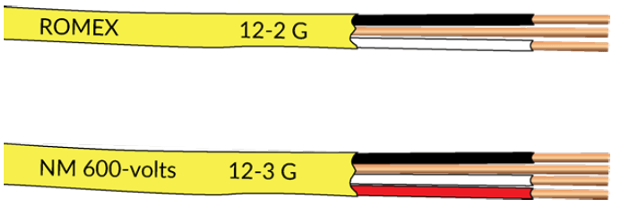
Romex Cable.
The National Electrical Code (NEC) stipulates a maximum bending radius for NM cable that is five times the cable diameter during and after installation. This requirement is in place to prevent potential breakage or power leakage from the cable. When installing the cable, it should be aligned with a joist or threaded through holes cut into a joist framing member. The below table outlines common NM wire types and their rated amperage for typical household wiring applications.
Wire Gauge or Type
- 14-2 NM
- Rated Amperage: 15A
- Common Uses: Circuits for lighting
- 12-2 NM
- Rated Amperage: 20A
- Common Uses: Circuits for lighting and outlets, refrigerator
- 10-2 NM
- Rated Amperage: 30A
- Common Uses: Electric water heater, baseboard heaters
- 10-3 NM
- Rated Amperage: 30A
- Common Uses: Electric clothes dryer
The term ROMEX® is a registered trademark owned by Southwire Company, LLC.
Service Entrance or Feeder Cable
Service entrance (SE) cables, as depicted in image below, incorporate either aluminum or copper conductors. These conductors transmit power from the service drop to the meter base and, if necessary, to the distribution panelboard. SE cable is suitable for both dry and wet installations above ground. SE cables are most commonly rated for 600 volts.

Service Entrance Cable
Image Courtesy of Southwire Company, LLC.
Metal Clad and Armored Cable
Frequently, Metal Clad (MC) cable (as shown in the below image) is the go-to choice for service power distribution, branch, and feeder, in a variety of settings including residential, institutional, industrial, and commercial. The applications of MC cable are typically those that demand 600 volts or above. The convenience of using MC cable indoors lies in the fact that it does not require a conduit. It also incorporates an insulated green ground wire, a departure from the traditional bare copper grounding conductor.

Metal Clad Cable
Armored cable (AC), also known as BX cable, has a unique feature where its metal sheathing can serve as a grounding conductor, setting it apart from the typical MC cable.
Underground Feeder
Underground feeder (UF) cables are exceptionally resistant to moisture, making them the perfect choice for outdoor lighting or applications that are buried underground. UF cables are encased in a solid thermoplastic that houses the wires collectively. They are available in multiple gauge sizes from 14 AWG to 6 AWG.

Underground Feeder Cable
Circuit Breakers and Fuses
Circuit breakers provide protection for high voltage residential wiring and are typically installed in a breaker box. They come in several types, including single pole breakers, double-pole breakers, ground fault circuit interrupters (GFCI) breakers, ARC fault breakers, surge protectors, and fuses.
Single Pole Breakers
Single-pole circuit breakers, which are quite common in residential settings safeguard a single 120V circuit and are usually rated at 15A or 20A. A 15A breaker is typically used to protect a 14 gauge NM circuit for lighting or outlets, while a 20A circuit breaker is generally used to safeguard a 12 gauge NM circuit. A single-pole circuit breaker occupies a single slot in a breaker panel and has one screw to connect the line wire (usually black).
Double Pole Breakers
Double-pole circuit breakers, another common type found in homes protect the 240V circuits in a house such as those found in a range, oven, air conditioner, water heater, or electric clothes dryer. Unlike a single-pole circuit breaker that often feeds a branch circuit with multiple outlets or light fixtures attached, double-pole breakers are usually point-to-point for the appliance being protected. Therefore, these circuit breakers are labeled in the break panel for the appropriately protected device.
Double-pole circuit breakers typically start at 30A, but can go as high as 100A, or more. Selecting the proper amperage on a circuit breaker is key to protecting the down-stream wiring and preventing electrical fires in the home. Do not replace a breaker in the panel with a higher amperage breaker under any circumstances. For example, if a circuit is originally sized at 30A for a standard water heater, a later upgrade to an on-demand water heater requiring a 60A circuit cannot be used in the same panel slot, since it will overload the wiring and possibly be a fire source.
Double-pole circuit breakers have two screws for attaching line wires. The red and black wires from a 240V appliance can be attached to these terminals. The double-pole circuit breakers will take up two slots in a breaker panel.
Guidelines for Electrical Wiring
The National Electric Code (NEC) governs the requirements for wiring, with new versions of the codes being released every few years.
Kitchen Wiring Codes
The subsequent points outline essential wiring codes applicable to kitchens:
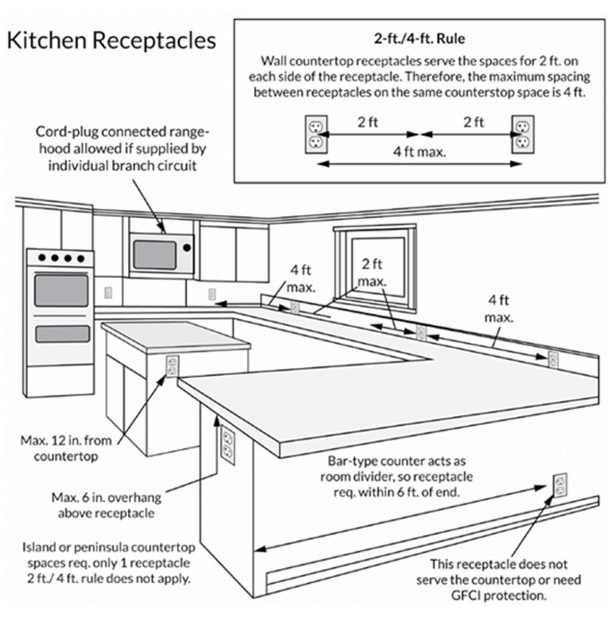
- For portable appliances in kitchens and dining areas, at least two 20-amp small appliance branch circuits must be provided. These circuits are additional to the ones that power lighting or permanently installed appliances. The short cords of portable kitchen appliances make it unlikely for them to be strung across sinks or cook tops. A receptacle should be in place for every countertop that is a foot or more in width.
- Both circuits should power outlets above the kitchen counter (for countertop appliances) instead of a single circuit. These outlet circuits should not provide power to any other lights or outlets in the house.
- It's advisable to have a refrigerator on a separate branch circuit, which can be connected to small appliance branch circuits in the kitchen.
- A dishwasher should have a branch circuit separate from other small appliance circuits. The dishwasher branch circuit (either receptacle or hardwired) must have GFCI protection.
- Countertop receptacles need to have GFCI protection.
- Receptacles should be placed in such a way that no point is more than 24 inches from a receptacle. Refer to the 2-ft/4-ft rule depicted in the below image.
- Receptacles can be set at a height of no more than 20 inches above the countertop.
- If the countertop on a peninsula is longer than 24 inches and narrower than 12 inches, measured from the connecting edges, receptacles are required.
- Island and peninsula countertop spaces must have at least 1 receptacle per space - the 24-inch rule is not applicable here.
- If an overhang of maximum 6 inches exists, without a backsplash or means of installing the receptacle above the countertop, island and peninsula receptacles can be installed no more than 12 inches below the counter.
- Code does not allow receptacles to face up on countertops.
- The space behind the sink or range is not considered a countertop space if it is less than 12 inches for a straight wall or less than 18 inches for a corner appliance.
Kitchen Receptacles Rule
Appliance Wiring Regulations
- Individual circuits are necessary for each built-in appliance like cooking ranges, dishwashers, or central air conditioning systems.
NOTE: As per NEC 2014, GFCI protection is required for all dishwasher branch circuits, irrespective of whether they are receptacle or hardwired.
- A designated 20-amp circuit is needed for the laundry outlet that is within 6 feet of the appliances. In addition, a separate dedicated 240-volt circuit is needed for an electric dryer.
NOTE: According to NEC 2014, all 125V, single-phase, 15- and 20-amp receptacles in laundry areas must include GFCI protection.
Outlet Wiring Regulations
The following are some common outlet wiring codes that apply throughout the house (refer to the below image):
- For every 575 square feet of house floor area, one lighting/convenience outlet circuit is required.
- Any bathroom or garage outlet within 6 feet of a sink must have GFCI protection.
- Outlets in bedrooms should include an ARC-Fault Circuit Interrupter (AFCI).
- At least one GFCI outlet should be installed in an unfinished basement and most outdoor outlets, with the exception of outlets that are unreachable, such as those located in a garage ceiling or behind a fridge.
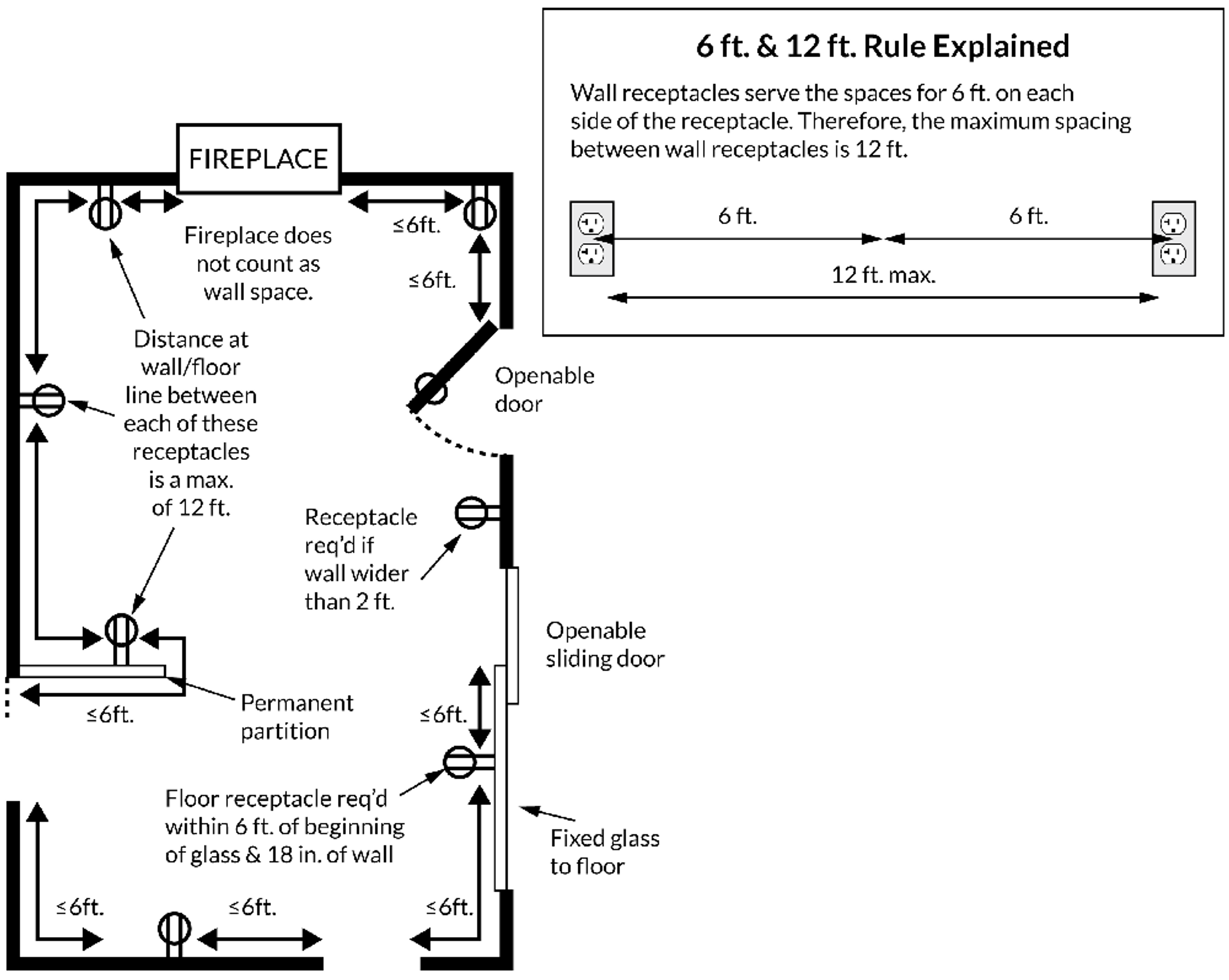
- Any wall that is 2 feet or more in length should have a receptacle.
- Counters and partitions in the form of bars are treated as walls.
- Doorways and fireplaces are not counted as walls.
- A receptacle must be placed within 6 feet from any point on a wall.
- For hallways that extend beyond 10 feet, outlets are necessary.
- Receptacles should be installed at a height of less than 5-1/2 feet.
- Floor receptacles that are located over 18 inches from a wall do not contribute to the total number of required receptacles.
Explanation of 6 ft. and 12 ft. Rule
GFCI Wiring Code Requirements
Here are the wiring codes for all 15A and 20A outlets on 120V circuits.
NOTE: These codes don't apply to 240V outlets or 30A 120V outlets:
- GFCI is mandatory for all bathroom outlets, as per the code.
- GFCI is necessary for all garage and accessory building outlets, except for those in garages and basements that are not easily accessible or those serving appliances such as freezers.
- All outlets in unfinished basements must have GFCI.
- GFCI is required for all outdoor outlets.
- GFCI is mandatory for all outlets in crawl spaces at or below ground level.
- Kitchen counter outlets must have GFCI.
- Outlets within 6-ft of the exterior edge of laundry, utility, or wet bar sinks must have GFCI.
NOTE: According to NEC 2014, additional areas requiring GFCI protection include:
- Outlets in laundry rooms.
- Dishwasher outlets or hardwired GFCI must be conveniently accessible.
Bathroom Wiring Codes
Here are the typical wiring regulations for a bathroom:
- Wall outlets must be installed within a 3-ft radius of each basin, or can be fitted on the side or face of a cabinet as long as they are less than 12 inches beneath the countertop.
- Outlets should not be installed face-up on vanity countertops.
- Outlets should not be installed within or directly above bathtubs or showers.
- Bath receptacles should have their own 20A circuits, or each bathroom should have a dedicated 20A circuit.
Laundry Wiring Codes
Here are the standard wiring regulations for a laundry room:
- At least one 20A circuit is required for laundry receptacles.
- The laundry receptacle circuit should not have any other outlets.
- An electric dryer needs a separate 30A circuit (10AWG copper).
Outdoor Wiring Codes
Here are the standard wiring regulations for outdoor outlets:
- Outlets that are reachable from grade level should be installed at the front and rear of the dwelling, and should be no more than 6-1/2 ft. above grade.
- Balconies with interior access exceeding 20 sq. ft. must have receptacles.
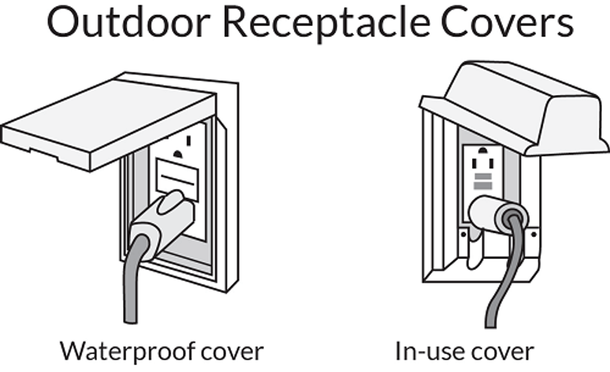
- Receptacles in damp or wet locations should be weather-resistant.
- Outdoor damp location receptacles (e.g., covered decks) need a weatherproof cover.
- Wet locations with a 15A or 20A receptacle require in-use covers, see the below image for details.
Outside Receptacle Covers
Regulations for Wiring Light Switches
Various residential light switches adhere to the following conventional wiring codes:
- Lighting outlets controlled by wall-switches are mandatory in all living spaces and bathrooms.
- Except in kitchens and bathrooms, lighting outlets in habitable rooms can be switched receptacles.
- Lighting outlets controlled by wall-switches are required in hallways, stairways, attached garages, and separate garages with electricity.
- If there are six (6) or more stairs, interior stairs require switches at each entrance.
- Lighting outlets must be placed on the exterior side of grade-level doors.
- Egress doors in garages must have lighting outlets.
- Lighting outlets aren't necessary at garage vehicle doors.
Electrical Calculations
The electrical segment of the examination includes performing basic electrical computations. Many of these calculations apply Ohm’s Law. The frequently used electrical symbols and abbreviations include:
I - This represents the current and is quantified in Amperes (A).
V, E - These signify voltage and are quantified in Volts (V).
R - This indicates resistance and is quantified in Ohms (Ω).
P, W - These denote power and are quantified in Watts (W).
Whenever electricity is flowing through a conductor, the following three elements always exist:
- The potential difference across the conductor, measured in Volts (V), which prompts the flow of the current.
- The resistance (R) of the conductor, measured in ohms (?), which impedes the current.
- The strength of the current (I), measured in Amperes (A), which is achieved by overcoming the resistance.
To solve electrical problems, use the relationship between these elements. The key formulas are:
- P = V × I (Power equals Voltage times Current)
- V = I × R (Voltage equals Current times Resistance)
- I = P ÷ V (Current equals Power divided by Voltage)
- R = V ÷ I (Resistance equals Voltage divided by Current)
EXAMPLE: When applying 1500 watts to a 120 V circuit, how many amps are consumed?
Identify which pyramid (formula) should be applied. By examining the question, identify which values are provided and which are being sought. In this example, the values for P (watts), E (volts), and I (amps) are being used. Therefore, the left pyramid (formula) will be applied. Cover “I” (amps) and divide “P” (watts) by “E” (volts).
1500 Watts ÷ 120 Volts = 12.5 Amps
Residential Electrical Service
In California, a permit is essential for the implementation of electrical services. Any proposed changes to the electrical service work can be modified by the utility company or a governing authority. A 240V service, obtained through two 120V lines and one neutral line, is typically supplied by the utility company to a residential building.
The smallest service size for a residential home is 100A. However, most contemporary homes have a 200A electrical service. The amperage availability determines the size of electrical services. Due to cost considerations, residential electrical services are commonly fed by aluminum conductors instead of copper. The utility company is responsible for determining the appropriate size, supplying the conductors, and installing the conductors in the conduit to the home's electric meter.
Service Panel
Power is supplied to the main panel through four wires. Three of them are supplied by the utility company, and an additional fourth (bare) wire may be sourced externally. This fourth bare wire is the "grounding conductor" and it's connected to:
- one or more metal rods embedded in the ground,
- a wire/rebar buried within the house foundation, or
- the water supply pipe (if the pipe is metallic) at the point where the main water pipe enters the house.
The grounding conductor's role is to ensure proper grounding of the third prong on all electrical outlets. This wire does not carry a current.
The neutral wire, often white, is connected to the grounding conductor in one location, usually within the main panel. The neutral and ground wires should not be connected anywhere else. Also, a home should only have one grounding system.
The remaining two wires, typically black, are the "hot" wires, connected to the utility company's distribution transformer. These two black wires are 180 degrees out of phase with each other, resulting in a voltage of 240V when both hot wires are connected. Connecting the white wire with either of the two black wires will yield a voltage of 120V.
In some panels, only three entry wires are visible because the neutral or ground wires are connected elsewhere (e.g., at the meter or pole), and one wire is serving both as neutral and ground. In rare cases, the service has only one hot wire (a 120V only service).
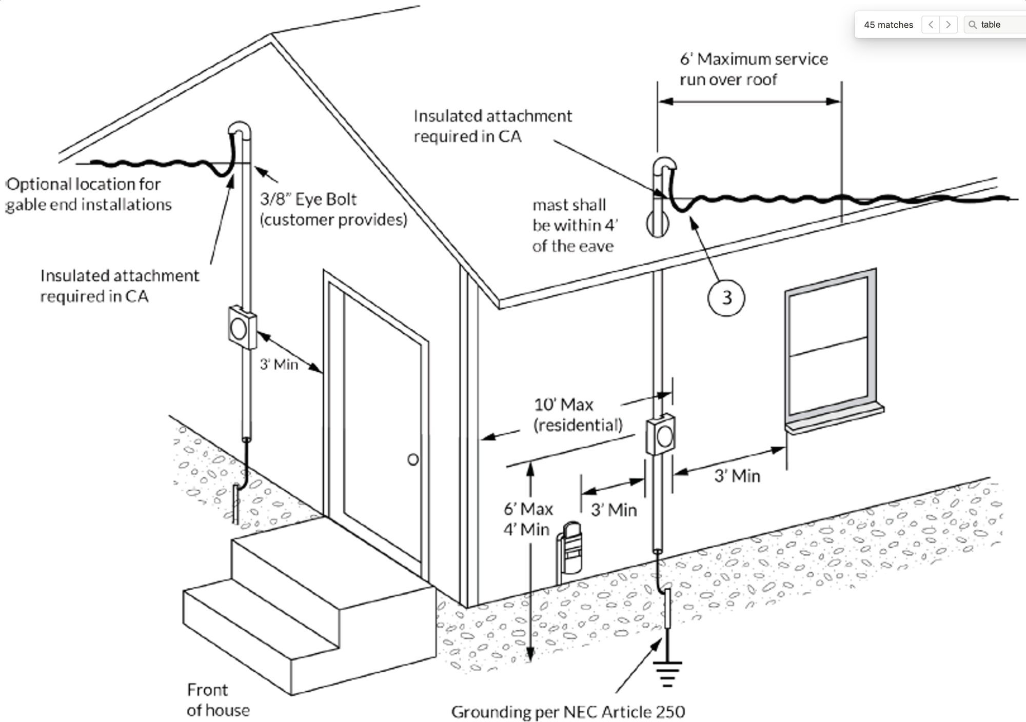
Power Meter - Clearances for a Building Supporting an Overhead Service
As shown in the below image, the power meter should be located at least three (3) feet away from an entrance door, gas meter, or window opening. Moreover, the meter should be positioned within 10 feet of the front corner of the residence.
Power meter placement
GFCI (Ground Fault Circuit Interrupter)
A Ground Fault Circuit Interrupter, also known as a GFCI, is a device that checks the current balance between the hot and neutral conductors in a circuit. In a normal situation, the current that flows out on the hot wire should return on the neutral wire. When the GFCI detects a current difference of a few milliamps, it assumes that the current is leaking elsewhere, typically to the ground, causing the circuit to trip. This unintended ground leak could occur through an appliance's chassis or even a person, making GFCIs a crucial safety measure, especially in areas prone to water exposure.
The common 120V GFCI outlet, as shown in the below image, has two vertical slots with a round ground hole located below them. The left slot (neutral) is slightly larger than the right one (hot). If an appliance is functioning correctly, all electricity used by the appliance will flow from the hot to the neutral wire. The GFCI is designed to track the current flowing between the hot and neutral wires. If any imbalance is detected, the circuit is tripped. It's sensitive enough to detect an imbalance as small as 4 or 5 milliamps and can respond in as little as one-thirtieth of a second.
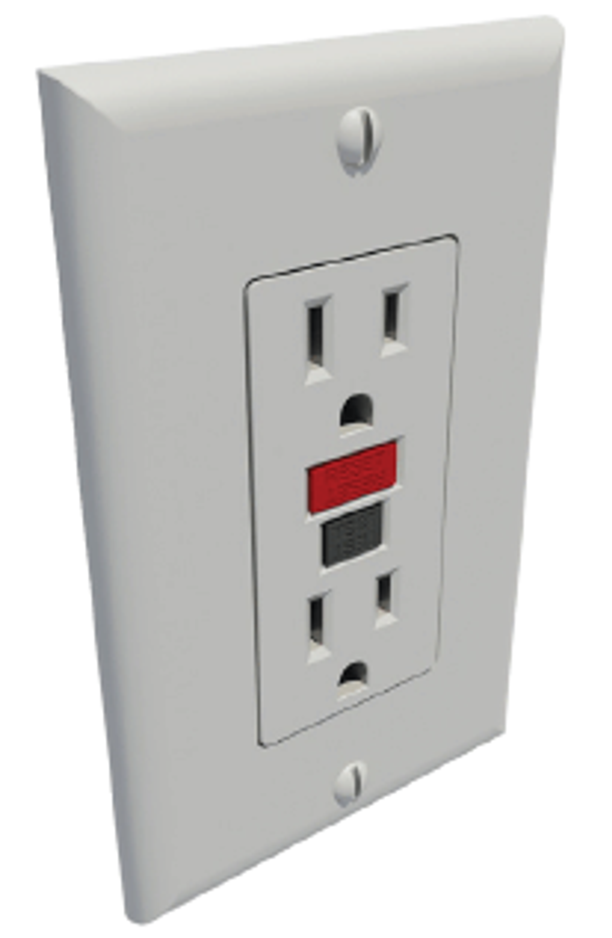
GFCI Outlet
Take note that a GFCI protected outlet, while designed to detect current leakage to the ground, may still allow for an electrical shock. This can occur if the hot and neutral lines are simultaneously touched, which could lead to electrocution as the current returns to neutral without causing the GFCI to trip.
In scenarios such as pool or hot-tub applications, the use of a multi-pole GFCI breaker may be needed. However, these are quite expensive, with prices often running into hundreds of dollars, depending on the panel box brand. In instances where such a circuit needs protection (like a pool heater), the options can be limited.
It's worth mentioning that GFCI outlets are rather large and might necessitate an oversized box for installation. A single GFCI outlet can be installed on the conductor, eliminating the need for additional GFCI outlets downstream on the same line. However, it's advisable to have all outlets GFCI protected.
During a GFCI installation, it's advised to use the accompanying “ground fault protected” stickers to mark the outlets downstream of the GFCI. You can identify the “downstream” outlets by tripping the GFCI using the test button and checking which outlets lose power.
Grounding the electrical system
Grounding's main objective is to minimize the risk of a severe electric shock from current leakage into the unshielded metal parts of an appliance, power tool, or other electrical device. In a properly grounded system, this leaking current (known as fault current) is safely dispersed. Despite most electrical systems having fuses or circuit breakers for protection against a significant fault current or short circuit, a current of less than one ampere can fatally shock a human body, well below the point where a fuse or breaker will activate. Grounding helps to prevent this kind of hazard. In some situations, like when a person handles an electrical device while standing on a wet surface, there's a risk of fatal shock from a leaking current, even from a correctly grounded electrical circuit. A GFCI is installed in the circuit for protection against this risk.
Most homes have their wiring system permanently grounded to a metal pipe entering the house from an underground water-supply system or to a metal rod driven into the ground. A copper conductor links the pipe or rod to a set of terminals for ground connections in the home’s electrical service panel. In wiring systems that use a metal-sheathed electrical cable, the metal sheathing typically serves as the ground conductor between wall outlets and the service panel. In wiring systems that use a plastic-sheathed cable, an extra wire is used for grounding.
An appliance intended to be grounded comes with a three-wire cord and a three-pronged plug designed to fit into a corresponding outlet. The third wire and prong establish the ground link between the metal frame of the appliance and the ground of the wiring system. Appliances like toasters with exposed heating coils shouldn't be grounded, as grounding could potentially increase the risk of an electric shock. Double-insulated power tools and small appliances have specially insulated casings that eliminate the need for grounding. They are designed so no exposed part of the device will be electrically live even if the internal insulation fails. Lightning protection using lightning rods and other means is also a form of grounding.
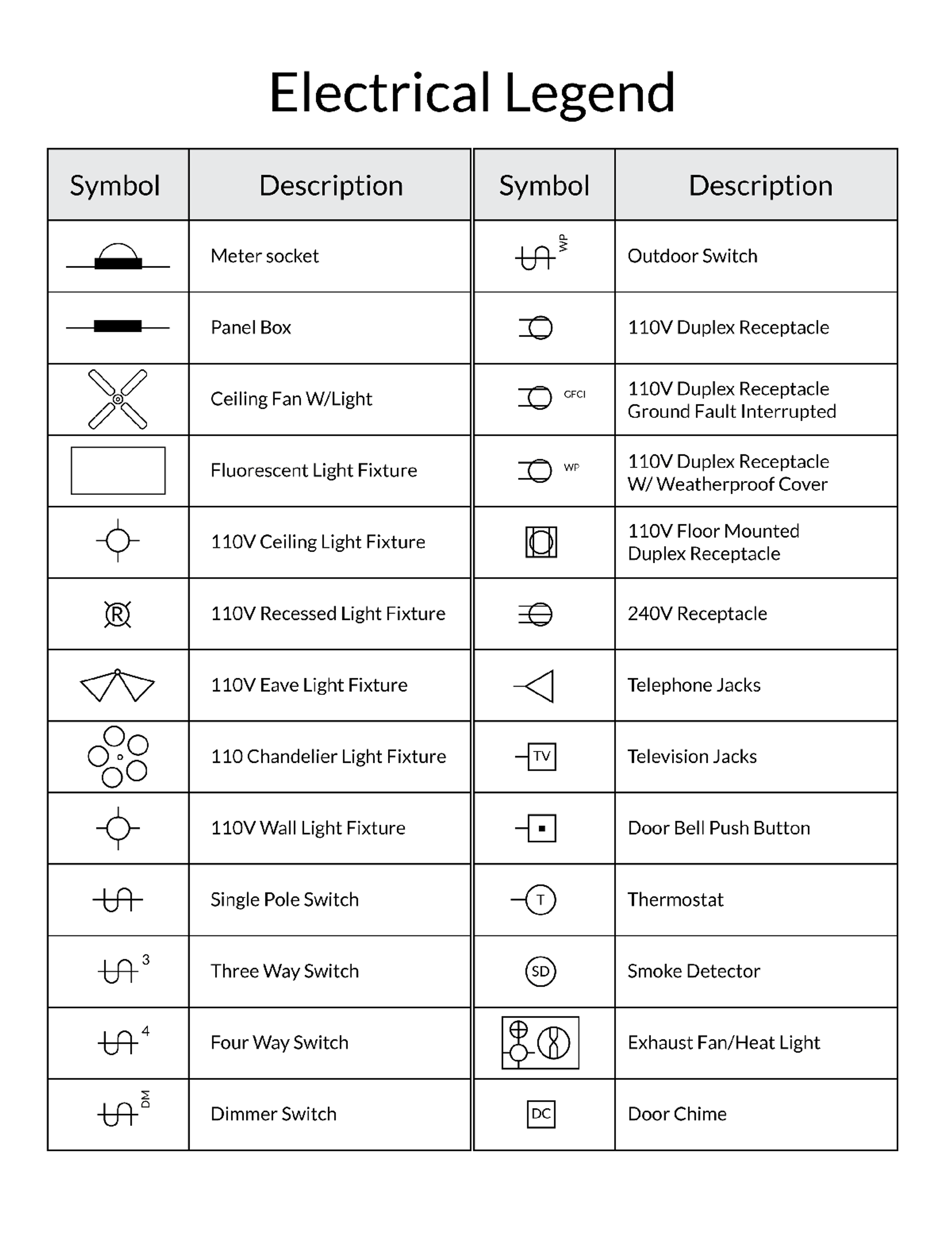
Electrical Legend
HVAC
HVAC Intro.
In California, Heating Ventilation and Air Cooling (HVAC) systems for residential construction generally follow national trends. The state is known for its eco-consciousness and cutting-edge systems when it comes to cooling and refrigeration. However, standard air supply tools and ducting practices are still commonly used. Eco-friendly systems are utilized in specific cases, primarily at the building owner's request.
Ductwork
The location of the furnace greatly impacts the design of the ductwork. Furnaces are typically installed in either the attic or the garage. If situated in the garage, the furnace usually needs longer ducts, leading to higher energy consumption. To minimize this, it's quite common in California to place the furnace in the attic, even though it requires a winch for installation. There should be a minimum clearance of 3 inches around the furnace for servicing or removal, and at least 24 inches of floor space from the attic entrance to the furnace service platform.
The placement of registers is determined by the zone control plan designed by the contractor. Common arrangements include:
- A 2-way register is the preferred choice when a register is to be positioned over a window or external wall.
- A register near an internal wall could employ either a 1-way or a 3-way register, with the primary direction aiming towards an external wall or window.
- For a register located in the middle of a room, a 4-way register is ideal as it accommodates interior decoration and the positioning of light fixtures.
Ducts are predominantly made from sheet metal and should be installed a minimum of 4 inches off the ground. If the duct is embedded within concrete slabs, it should be encased with at least 2 inches of concrete. If rectangular ducts need to be suspended, their supports should be securely riveted, bolted, or screwed to both sides of the duct. For round ducts, they should be less than 40 inches in diameter and fit snugly around the perimeter. Regardless of the duct's shape, ducts should never be directly connected to registers at a 90-degree angle. In such cases, a special transition fitter like a rectangle box should be used.
Sizing Basics
A useful initial step in sizing air conditioning (AC) equipment is to calculate the total square footage of the rooms. The relation between the gross floor area and the Btu/h capacity is shown in the below image. It's important to consider that these numbers can be influenced by factors such as:
- House orientation – subtract Btu requirement for north or south-facing houses while increase for east and west orientations.
- Whether the area is sunny or shaded, poor insulation can increase Btu by up to 15%.
- Presence of kitchens – can add up to 4000 Btu/h
- Occupancy of the house – each individual adds approximately 400-600 Btu.
- Daily usage.
Size of Room
- 150 sq. ft.: 5,000 BTU/h
- 300 sq. ft.: 8,000 BTU/h
- 450 sq. ft.: 10,000 BTU/h
- 700 sq. ft.: 14,000 BTU/h
- 1200 sq. ft.: 21,000 BTU/h
- 1600 sq. ft.: 32,000 BTU/h
In California, it's typical to utilize a single HVAC system for a two-story house. This highlights the significance of optimal design and leakage control to avoid major adjustments after a few months of occupancy. Generally, a three-ton AC unit can provide a cooling capacity of 36,000 Btu/h.
A unit ton of AC capacity is equivalent to 12,000 BTU/hr
Furnace Size Determination
The task of finding the right furnace size for homes is often carried out by heating and air conditioning professionals. They employ various load calculations to ensure accurate results. However, for a general estimation, a furnace that can produce 20 BTUs per square foot is often recommended. Given this approximation, a home with an area of 2,500 square feet would require a furnace with a capacity of 50,000 BTUs.
Understanding Refrigerants
Refrigerants are chemicals used in cooling systems that can be highly flammable and potentially harmful to human health. As a result, their usage and handling must be regulated. The building code includes a list of various refrigerants along with the maximum allowable quantities based on the system and area of the room.
R-22 is a refrigerant frequently found in older air-conditioning systems. The Clean Air Act mandates that R-22 refrigerant must not be released into the atmosphere during the installation, maintenance, or decommissioning of equipment. Newer air-conditioning systems often use R-410A refrigerant as a replacement for R-22.
Existing units that use R-22 can continue to be serviced with R-22, as there is no EPA regulation requiring R-22 units to be converted for use with non-ozone-depleting substitute refrigerants. These conversions, known as "retrofits," are allowed if an approved alternative has been identified. R-407C is permitted for retrofits, but R-410A is not due to its higher operating pressures.
Concrete
Formwork
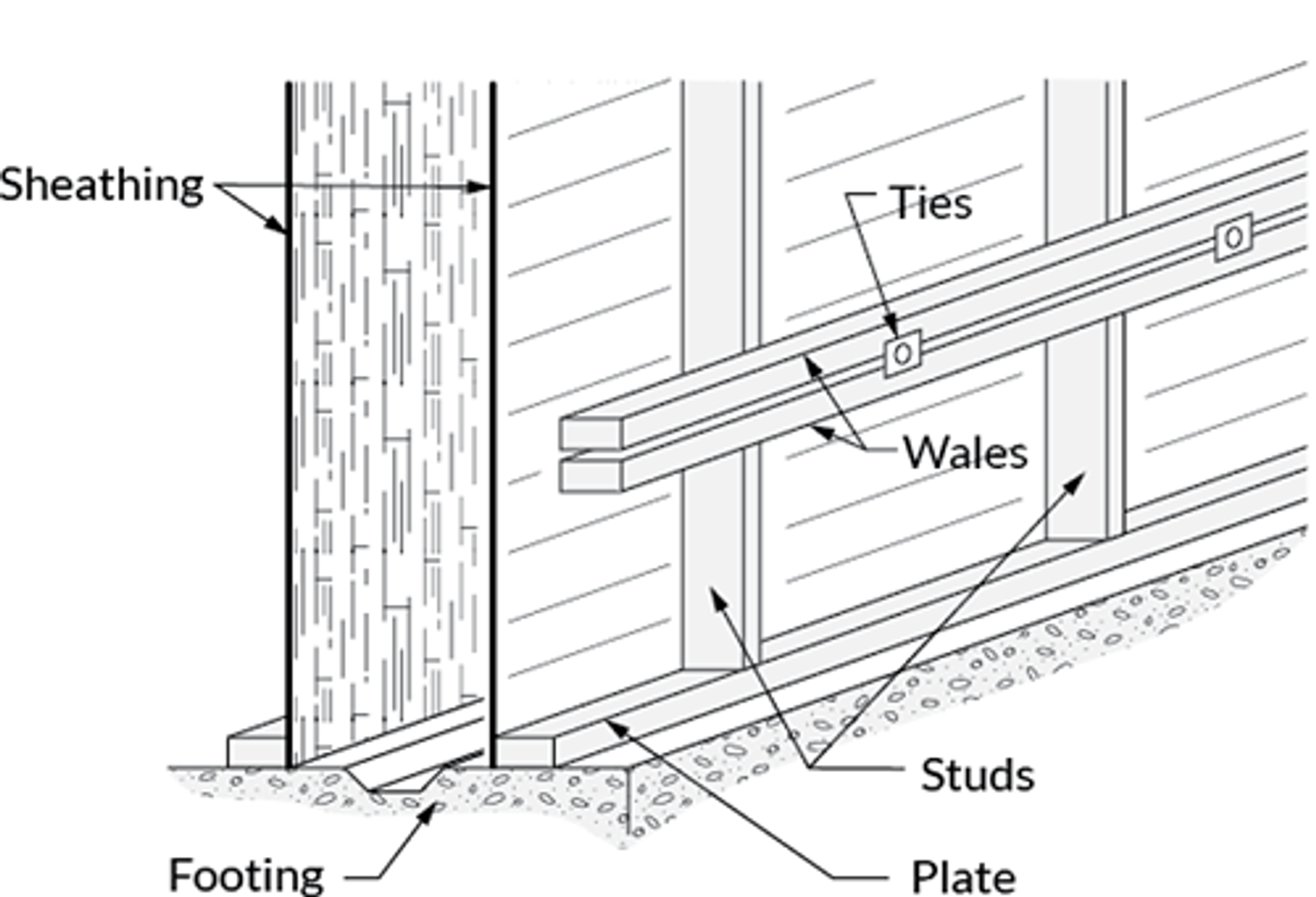
Formwork involves creating moulds which will shape the concrete during the pouring process. This is often the first duty carried out by a construction team on a project. Post the trench excavation that outlines the building, the forms are set within these trenches to facilitate a structured concrete pour, resulting in a "footing" or the building's outline. At the same time, forms for structural support columns will also be installed. Some forms may need to be removed to complete any additional formwork required within the building outline.
The forms are secured using form boards and rebar stakes. For safety measures, rebar protruding from the ground should be covered with orange safety caps. As depicted in the below figure, the forms are set up to contain the poured concrete, which will be removed once the concrete has hardened.
Setting Up Concrete Forms
Footings
Footings serve a dual purpose as they provide structural support and prevent foundation settlement. They are integral for constructing multi-story buildings. Footings, made of rebar and concrete, are poured into trenches that have been dug beforehand to mitigate the problems associated with soil shifting or settling over time.
Depending on whether a building is 1, 2, or 3 stories, varying sizes of footings are needed. The footing size is determined by the weight that the column needs to bear for the building. California has specific footing size requirements corresponding to the number of stories a building has.
Table: Required Footing Size: Soil's Load Bearing Value vs. Number of Stories
(measured in inches)
Soil Load-Bearing Value (psf):
- 1,500 psf
- 1-story: 12
- 2-story: 15
- 3-story: 23
- 2,000 psf
- 1-story: 12
- 2-story: 12
- 3-story: 17
- 3,000 psf
- 1-story: 12
- 2-story: 12
- 3-story: 12
- ≥4,000 psf
- 1-story: 12
- 2-story: 12
- 3-story: 12
The above illustrates the required dimensions of the footings (in inches) in relation to the load-bearing value of the soil, materials used, and the number of building stories, in compliance with California state building codes.
Footing Formwork
Upon completion of the footing excavation and cleaning, the forms are placed. The formwork for the footing enables the construction crew to shape the form, complying with the footing size requirements set by California. Form boards are used to measure out the footings and columns after the trench is dug. There are two distinct categories of formwork:
- Class I formwork is applicable to temporary or light loads.
- Class II formwork is used for structures that will bear heavy loads.
Footing Excavation
Following the building layout marking, the excavation for the footings starts. The footings should delve at least 12 inches below the soil surface for a 1-story building in undisturbed soil. The footings should extend beneath the frost line to avoid cracking due to frozen water.
Note: Footing sizes will need to be increased for 2 or 3-story buildings or if the soil has a lesser load-bearing value (LBV) weight.
A soil test can determine the LBV of the soil being excavated. The below information provides the LBV weight for different soil types.
Soil Type and Weight
Soil Type
- Mixtures of clay, silt, and sand: 2,000 pounds per sq. foot
- Combinations of sand, gravel, and clay: 3,000 pounds per sq. foot
- Gravelly or sandy compositions: 5,000 pounds per sq. foot
- Sedimentary rock: 6,000 pounds per sq. foot
- Bedrock: 12,000 pounds per sq. foot
The heavy lifting of digging footings is done by an excavator. Following the use of machinery, the crew manually refines the trenches to meet the exact specifications. Smaller interior footings may also be necessary, and these are typically dug by hand unless the excavator can reach them. The crew must continually clean the footing trenches during excavation to prepare them for concrete.
Rebar
Rebar, or reinforcing bar, enhances the concrete's tensile strength and ductility, making it less susceptible to cracking and degradation under stress. This is particularly crucial in areas like California that are prone to earthquakes. Rebar also improves the concrete's resistance to forces that could cause it to separate.
Deformed bars, commonly used, are made of carbon steel and feature external ridges for enhanced anchoring. They offer a high strength-to-weight ratio, are easily welded, and can be bent and shaped as required.
Rebar Size
Rebar is available in various diameters, measured in 1/8 inch increments. The standard diameter used is 1/2 inch (4/8 inch). To protect the rebar from corrosion and other environmental damage, it should be encased in at least 2 inches of concrete on all sides. Rebar thickness is represented by numbers ranging from #3 - #18, each corresponding to a specific thickness, as shown in below table.
Bar Size Designation
- #3: 3/8”
- #4: 1/2”
- #5: 5/8”
- #6: 3/4”
- #7: 7/8”
- #8: 1”
- #9: 1.128”
- #10: 1.270”
- #11: 1.41”
- #14: 1.693”
- #18: 2.257”
Reinforcing Main Fields
The distance between rebars depends on their location. In the main fields where floors are usually poured, the rebar should be arranged in an 18 x 18 inch grid. Along the edges, the grid should be tighter (15 x 18 inches) for additional support, as depicted in the below image. The intersections of the rebar should be secured with wire ties to prevent movement before the concrete sets.
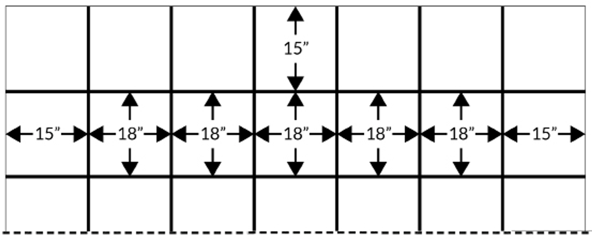
Rebar Grid Spacing
To ensure that the rebar is adequately coated by the concrete when poured, position the grid using chairs. This method is more effective than pushing the rebar into the concrete prior to it solidifying, or lifting the rebar grid during the concrete pour. The use of chairs is a requirement by the California State building code during this phase of construction.
The rebar that forms the grid is usually thin, with diameters ranging from 1/4 to 1/2 inch. For footings and columns that need structural support, the rebar used can be as thick as 1 inch.
Reinforcing Stem Walls
For concrete stem walls, two #4 rebar (1/2 inch diameter) should be installed - one 3 inches from the top and another 3 inches from the bottom of the footings. If these bars are over 18 inches apart, extra reinforcement is necessary to ensure that the maximum distance between horizontal bars does not exceed 18 inches. If the stem wall exceeds 2 feet above the footing or if cold joints appear in the construction, use #4 vertical bars spaced 18 inches on center (o.c.).
Rebar Overlap
Per the California building code, the standard overlap for rebar is determined by multiplying the diameter of the rebar by 30, as shown in the below table.
Diameter
- ½”: 15” overlap
- ¾”: 22 ½” overlap
- 1”: 30” overlap
- 1 ½”: 45” overlap
- 2”: 60” overlap
Concrete Slabs
The thickness of concrete slabs should be at least 3 1/2 inches. For slabs intended for living areas or garages, they should be reinforced with a grid of rebar or wire mesh. A waterproof layer should be placed under the slab to separate it from the soil in living spaces. Footings for the concrete slabs should incorporate two rebars each measuring 1/2” in thickness for walls that will bear weight and openings for garage doors. Refer to the below image for further details.
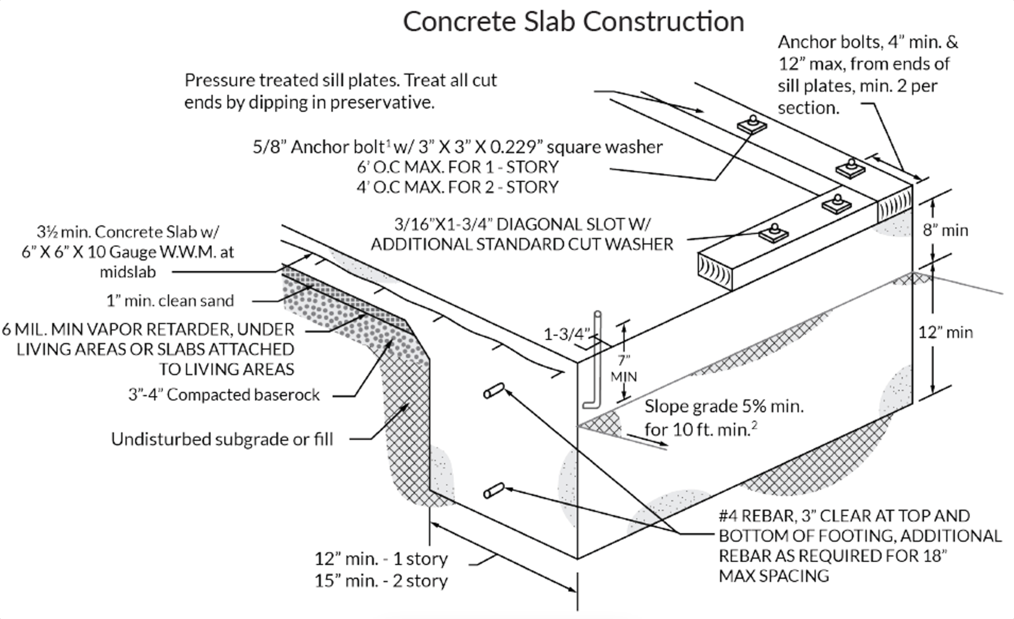
Notes:
- The size of the anchor bolt is predicated on the assumed seismic design category (SDC) E. However, 1/2" Anchor Bolts are also suitable.
- IF it is not possible to maintain a 10 FT. of horizontal distance due to physical obstructions or lot lines, the grade should be sloped at 5% or an approved alternative method should be used to divert water from the foundation. If the surfaces are impervious, or if the climate or soil conditions call for it, a 2% slope for a minimum of 10 ft. will be acceptable.
- The strength of all concrete should be a minimum of 2500 PSI. Adequate curing conditions should be provided.
Electrode Grounding within a Foundation
To achieve efficient grounding, the following standards must be adhered to when positioning an electrode within a concrete foundation:
- The electrode must be enclosed by at least 2 inches of concrete.
- Placement of the electrode must be near or at the bottom of the foundation or footing.
- The concrete should have direct contact with the earth.
- A conductor, which can be either 20 feet of rebar with a minimum thickness of 1/2 inch or 20 feet of solid copper, should be used.
Concrete Pouring
When the site preparation is complete, the next step is to pour the concrete. Typically, the concrete is brought to the site in a concrete truck and can be poured directly from the truck into the previously prepared forms. Alternatively, a concrete boom truck may be used. This type of truck features a spout that delivers the concrete, allowing for greater precision and adaptability compared to pouring directly from a truck.
Upon pouring, a concrete vibrator is employed to eliminate any potential air pockets that might be trapped within the concrete and could weaken its structure. Following this, the construction crew will level and smooth out the concrete to ensure a flat, smooth surface.
Concrete Mixtures
In construction, there are various types of concrete mixtures that can be used, each having a specific purpose and differing in their water and sand/rock ratio. It's important to note that the minimum strength of the concrete for foundation construction must be at least 3,000 pounds per square inch after it has fully dried over a period of 28 days. The below bullets outlines the components of the four primary types of concrete mixture ratios:
- Rich Concrete: Ideal for the construction of concrete roads and waterproof structures.
- Standard Concrete: Commonly used for reinforced work on floors, roofs, columns, arches, tanks, sewers, conduits, and more.
- Medium Concrete: Suitable for building foundations, walls, abutments, piers, and the like.
- Lean Concrete: Typically used for all mass concrete work, large foundations, backing for stone masonry, and similar tasks.
Category
- Rich:
- Cement: 1 portion
- Sand (Fine Aggregate): 2 portions
- Coarse Aggregate: 3 portions
- Standard:
- Cement: 1 portion
- Sand (Fine Aggregate): 2 portions
- Coarse Aggregate: 4 portions
- Medium:
- Cement: 1 portion
- Sand (Fine Aggregate): 2.5 portions
- Coarse Aggregate: 5 portions
- Lean:
- Cement: 1 portion
- Sand (Fine Aggregate): 3 portions
- Coarse Aggregate: 6 portions
Types of Portland Cement and Applications
Portland cement comes in five different types, each with its specific uses. The below information provides a summary of these types of Portland cement.
Type I: Normal
- Purpose: This is the go-to cement for most general uses when the type of concrete isn't specified.
Type II: Moderate
- Purpose: Used when it's important to take precautions against moderate sulfate attack. Often utilized in drainage structures where sulfate concentrations in groundwater are above average.
Type III: High Early Strength
- Purpose: Chosen when high early strength is required. It's used when it's necessary to remove forms quickly or put the concrete into service rapidly. It also helps reduce the period of exposure to low temperatures to protect the concrete.
Type IV: Low Heat of Hydration
- Purpose: Used when it's vital to minimize hydration heat in large volume applications, such as gravity dams.
Type V: High Sulfate Resistance
- Purpose: Used as a safeguard against severe sulfate action, mainly where the soil or groundwater has a high sulfate content.
Mixing Concrete
For larger projects or constructions, it's advisable to hire a concrete service to mix and deliver the concrete to the job site. Small scale corrections to the quantity of concrete available can be made manually.
To mix concrete by hand, first determine the type of concrete required and purchase the dry cement mixture accordingly. To ensure the correct amount of cement is bought, calculate the volume of the area to be excavated. For instance, a one-square-foot slab (1’×1’×4”) will approximately need 40 to 50 pounds of concrete. It's advisable to overestimate the volume required by at least 10% to account for potential spillage and evaporation as the concrete dries. When ordering from a concrete delivery service, they usually divide volumes by 1/4 cubic yard.
Curing Times
Various elements influence the duration it takes for concrete to dry. These include the ratio of water to cement, particle size within the cement blend, the mixture's chemical composition, and the presence of any concrete admixtures. The quantity, particularly the depth of the pour, significantly affects the drying time of concrete. More extensive and deeper pours entail a longer drying period. Refer to the information below.
In construction, two concrete set times are utilized:
Initial Set Time occurs when the concrete substantially hardens but is not yet ready to bear weight reliably. At this stage, it is safe to remove the forms, typically a few hours after pouring.
Final Set Time is the point when the concrete has hardened to such an extent that it cannot be manipulated further and can bear a substantial amount of weight. This usually takes 1-2 days.
NOTE: Complete curing of the concrete does not occur until 28 days after pouring. Heavy objects should not be placed on the concrete until at least 7 days after pouring, and heavy machinery should not be used until 28 days have passed.
Drying times:
Drying Time: 2-4 hours
- State: The concrete starts to set, but cannot bear any weight. The top of the concrete can be finished.
Drying Time: 24 hours
- State: The concrete should support a person's weight, but it is still susceptible to smudging and indentation if a moderate amount of weight is applied or if it is subjected to heavy foot traffic.
Drying Time: 3 days
- State: The concrete should tolerate normal foot traffic, but cannot bear heavy loads at this point.
Drying Time: 7 days
- State: The concrete should bear heavier loads and is nearing its maximum load-bearing capacity. Heavy machinery should not be used on the concrete.
Drying Time: 28 days
- State: The concrete has fully hardened and cured, and can effortlessly support up to its maximum load capacity. Heavy machinery can be used on the concrete.
Full Concrete Process
The initial step in the comprehensive concrete process involves preparing the site, which includes:
- Clearing the area;
- Flattening the floor regions;
- Excavating the trenches;
- Setting up the forms;
- Positioning rebar throughout the area designated for the concrete pour;
- Lifting the rebar;
Upon pouring the concrete, it needs to be leveled and smoothed. The forms can be taken off during the drying process. However, the forms must stay in place until the cement has achieved a specific hardness. Also, the cement cannot be completely smoothed until it has reached a certain hardness level.
The process of smoothing the cement involves multiple steps that must be carried out with the appropriate equipment and timing. If not timed correctly, the cement could dry too rapidly, making it unfixable later on.
Finalizing the Concrete Surface
The completion of a concrete pour surface involves multiple steps.
Screeding
During screeding, a screed, which is a long beam or flat board made of aluminum or wood, is used to even out and flatten the concrete surface post-pour. This process is essential in smoothing the concrete.
Bull Floating
Bull floating is another method used to create a smooth and flat finish on the concrete surface. A bull float tool, which comes in various sizes, is used to level out the top of the concrete.
Edging
Edging is a process that compacts the concrete along the form where bull floating and troweling may not be as effective. It strengthens the slab's edge, reducing the likelihood of chipping and scaling.
Jointing
Jointing involves creating intentional cracks in the concrete to manage potential cracking due to temperature fluctuations that cause expansion and contraction over time. As commonly observed on sidewalks, joints should be spaced 2-3 feet apart for every inch of slab thickness. For example, on a 4” concrete slab, joints should be spaced 8-12 feet apart. The depth of these joints should be 25% of the slab's thickness, which means a 4-inch slab should have 1-inch deep joints.
It's easier to cut joints before the concrete dries, which can also prevent potential cracking during the joint cutting process. If the concrete is too dry, a cement grooving tool will be needed. To keep the joints intact during drying, a spacer can be inserted into the cut joints. In hotter climates, joints should be cut within 12 hours of the pour's completion. Joints should be located at the start of any slopes in the concrete. The below diagram provides an example of appropriate joint spacing.
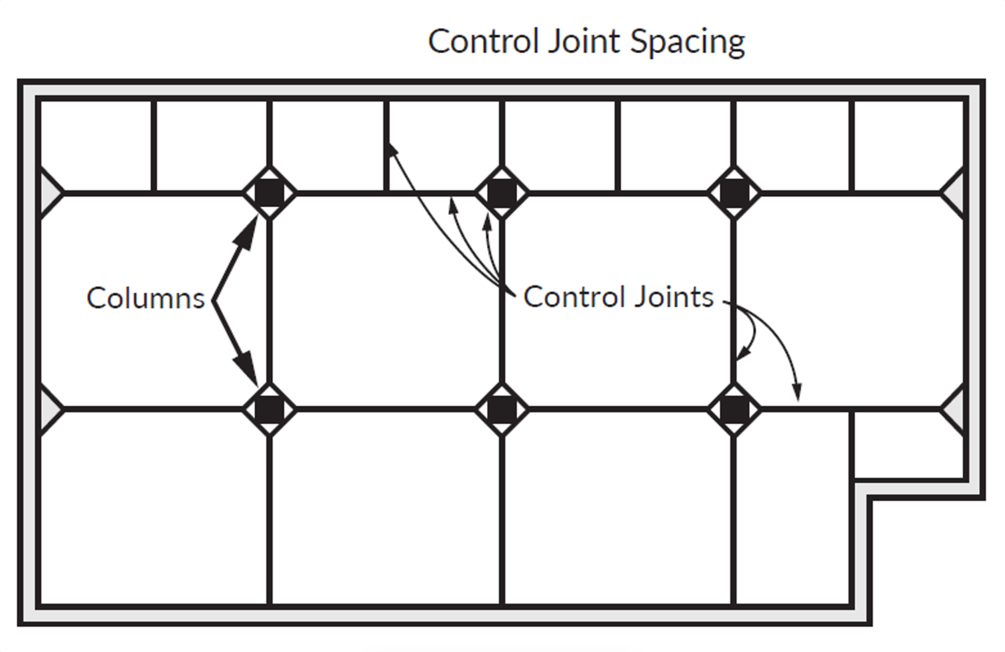
There are three distinct categories of joints:
- Control Joints commonly serve as spacing joints and are frequently observed on sidewalks.
- Isolation Joints are employed to segregate the concrete slab from other elements. These are usually used around walls, pillars, and deck posts extending from the slab. These joints prevent the expansion of the concrete from damaging other materials.
- Construction Joints are utilized in major projects where the slab cannot be laid with a single pour of concrete.
Troweling
Troweling is performed with a tool that resembles a float and is used immediately after floating. The difference between a trowel and a float is that a trowel has a firmer flat edge and is generally made from metal. Trowels are used to create a final robust, compact surface in the concrete. However, they should not be used to exert any pressure on the concrete.
Broom Finishing
The concluding stage of finishing concrete is broom finishing. Sweep the broom across the cement's surface to create small, uniform grooves. This process enhances the concrete surface's traction.
Slump Test
A slump test is a method to gauge the consistency of multiple concrete batch pours. This test is easy to conduct and necessitates a metal mold shaped like a traffic cone, known as an Abrams cone. The cone is filled with concrete in three stages, with the concrete compacted after each stage. Once the cone is fully loaded, the cone is carefully removed, and the amount of slump in the mixture is measured. The typical results of a slump test are depicted in the below image and described below.
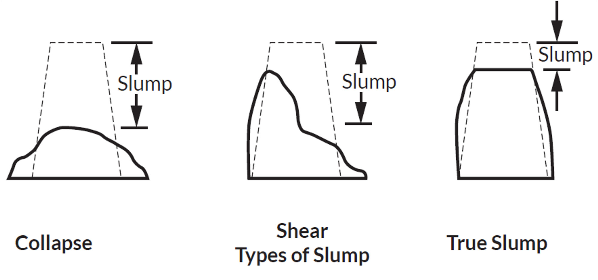
Type of Slump: Collapse
- Result: The concrete collapses on itself completely.
Type of Slump: Shear
- Result: The top of the slump collapses while the bottom remains firm.
Type of Slump: True
- Result: The concrete stays firm and retains its shape.
Earthwork and Surveying
Clearing and Preparing the Lot
The initial phase of any significant construction project entails lot preparation through comprehensive clearing and leveling operations. This ensures an efficient workspace for various work crews. Unused vehicles should be moved out, and all rubbish should be disposed of, facilitating accurate leveling tasks.
Ensure that all curbs and gutters are inspected and cleared to allow for effective drainage of rainwater. During construction, drain blockages frequently occur; therefore, maintaining clear drainage systems is vital. This also prevents the contamination of public water systems with pollutants from the construction site.
Underground Service Alert
The Underground Service Alert is a complimentary public service offered throughout California. This service oversees damage prevention activities and reviews all excavation plans, dispatches a crew to mark specific areas, and provides property-related information to the owner and construction crew. They also caution about anything that needs to be considered before work starts and indicate the position of underground utilities accessing the property.
The Underground Service Alert should be informed no earlier than 14 days and at least 2 days before the start of excavation. Any operator or excavator failing to inform Dig Alert before excavation due to negligence is liable to a civil penalty not exceeding $10,000.
- Negligence in notifying the Underground Service Alert can result in penalties up to $10,000.
- Deliberate failure to notify the Underground Service Alert can attract penalties up to $50,000.
As areas are marked, a system of color-coded stakes and markers, along with abbreviations, is used to denote each type of facility. The color code and facility identifiers are specified below.
Color: White
- Interpretation: Planned Excavation
Color: Red
- Interpretation: Electrical Power Lines, Cables, Conduit, and Lighting Cables
Color: Orange
- Interpretation: Telecommunication, Alarm, or Signal Lines, Cables, or Conduit
Color: Purple
- Interpretation: Recycled Water, Irrigation, and Slurry Lines
Color: Pink
- Interpretation: Temporary Survey Markings
Color: Yellow
- Interpretation: Gas, Oil, Steam, Petroleum or Gaseous Materials
Color: Blue
- Interpretation: Drinking Water
Color: Green
- Interpretation: Sewage and Drainage Lines
Symbol: CH
- Interpretation: Chemicals
Symbol: E
- Interpretation: Electricity
Symbol: FO
- Interpretation: Fiber Optic
Symbol: G
- Interpretation: Gas
Symbol: LPG
- Interpretation: Liquefied Petroleum Gas
Symbol: PP
- Interpretation: Petroleum Products
Symbol: RR
- Interpretation: Railroad Signal
Symbol: S
- Interpretation: Sewage
Symbol: SD
- Interpretation: Storm Drain
Symbol: SS
- Interpretation: Storm Sewer
Symbol: SL
- Interpretation: Street Lighting
Symbol: STM
- Interpretation: Steam
Symbol: SP
- Interpretation: Slurry System
Symbol: TEL
- Interpretation: Telephone
Symbol: TS
- Interpretation: Traffic Signal
Symbol: TV
- Interpretation: Television
Symbol: W
- Interpretation: Water
Symbol: W (Purple)
- Interpretation: Reclaimed Water
Property Leveling
Following clearance and utility marking, the property may require leveling to create a flat, even surface for the building's foundation. This process involves excavation and the addition of fill materials like soil, rocks, or concrete.
The property is surveyed and graded using survey stakes placed throughout the area, indicating the regions that need excavation or filling to level the lot.
When adding fill material, it's crucial to compact the soil to avoid settlement issues with the foundation later in the construction process. Moisturizing the fill and then driving over it with heavy construction machinery can achieve soil compaction. According to California building codes, fill material must be compacted to a minimum of 90%. Initially using excess fill material can account for the compaction process. As construction progresses, more fill material may be needed.
Soil Types
A wide array of soil types exist, and these greatly influence the excavation and soil compacting processes. It's advisable to engage the services of a soil expert to accurately identify and evaluate the type of soil present.
Soil can be categorized as granular or cohesive. Cohesive soil consists of clay and fine particles, giving it the ability to bind together. Depending on the clay content, cohesive soil can be more compact and self-adhering. Granular soil, on the other hand, comprises larger particles like sand or ground rock. This type of soil is loosely packed and might be susceptible to cave-ins during extensive excavation. Generally, soil types are classified into three categories:
Type A Soil is predominantly cohesive, capable of supporting substantial weight, typically 1.5 tons per sq. ft or more. It's the most stable soil type, with most clay-based soils falling under this category.
Type B Soil is a combination of cohesive and granular soils. The smaller particles bind together, giving support to the larger particles. It can withstand medium levels of compression, usually between 0.5 and 1.5 tons per sq. ft.
Type C Soil is largely granular and highly unstable. It can only bear low compression weights of 0.5 tons per sq. ft or less. This soil type, generally composed of sand or gravel, absorbs water easily.
The choice of soil to build on depends on the weight to be supported. Type A Soil is the best option, as it can bear a large amount of weight and is less likely to shift or sink during heavy rainfall. When constructing on Type B and Type C soils, it's crucial to ensure that the building plans do not exceed the soil's weight-bearing capacity.
Staking the Property
Stakes used should be highly visible, typically one to two feet tall with a brightly colored ribbon attached. The stakes will bear marks to signify if fill ("F") material is needed, or if material needs to be cut (C) or removed from the area. Additional markings on the stakes will indicate the quantity of material to be added or subtracted. Marks that identify the required grade level will also be present. For instance, "pad grade" (PG) will be used for the building's foundation. After the lot has been leveled in accordance with the grading stakes, the final outcome should be a flat leveled surface ready for the foundation.
Grading
Grading refers to the process of creating level or inclined ground within the project site. In most instances, flat grading will be required for the base of structures, while inclined grading will be used for drainage systems.
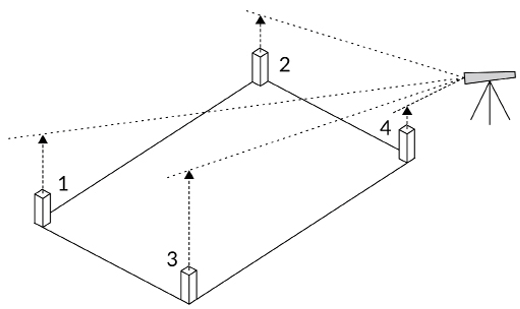
Utilization of Transit
The above diagram illustrates the process of grading, which is premised on a singular reference point, made possible through the use of a transit. Stakes initially placed across the terrain are elevated to align with the transit's original point.
Insulation, Acoustical and Weatherproofing
Proper insulation is a vital element in maintaining a comfortable environment within a home, as it helps regulate temperatures and shields the home from external weather conditions. Consequently, adequate insulation can lead to substantial energy savings for homeowners.
R-Values
The R-Value is a measure of the thermal resistance of insulation, indicating its capacity to prevent heat from passing through. When the material is homogeneous, the R-value typically increases with the material's thickness. The "R" in R-Value stands for resistance; hence, the higher the R-Value, the better the material is at resisting heat transfer.
One inch of fiberglass batt has an R-Value of 3.16, which is added for each additional inch of fiberglass. However, the R-Value per inch can vary depending on the material, as shown in the table below.
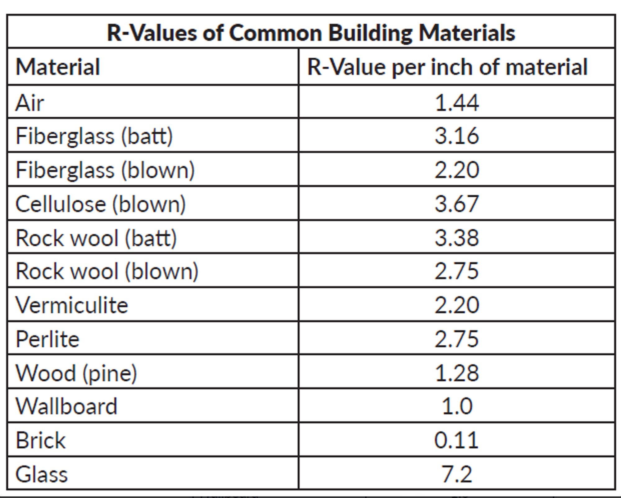
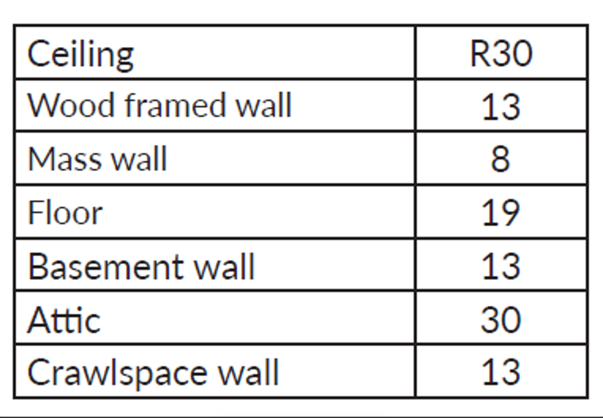
The choice of minimum R-Value material is influenced by the local climate and the specific area of the building that requires insulation. Different areas of a building have different minimum R-Value requirements. As displayed in the below table, these requirements vary by zone. For instance, in Central California, the minimum R-Value for attic insulation is 30, while wall insulation requires a minimum R-Value of 13, which can be achieved using batt or R-13 fiberglass insulation.
Fiberglass
Fiberglass, a prevalent insulation material, is often employed in the insulation of interior and exterior walls, as well as floors and ceilings. It comes in batts and rolls, both with and without a paper backing that serves as a vapor barrier, preventing ceiling and wall condensation.
Safety
When handling fiberglass insulation, airborne fiberglass particles are inevitable. It's crucial to avoid inhaling these particles and be aware that they can irritate the skin and eyes. Thus, protective gear such as gloves, long-sleeved shirts, long pants, eye protection, and a respiratory mask should be worn when installing fiberglass insulation.
Cellulose
Composed of recycled paper, cellulose insulation comes in a loose form. Its suitability for attic floors, walls, and confined areas stems from its ability to be blown into place. Although cellulose offers superior insulation compared to an equal volume of fiberglass, its settling over time reduces its insulating effectiveness.
Radiant Barrier Insulation
Commonly installed in attics, radiant barrier insulation is a type of reflective insulation aimed at maintaining indoor comfort during high outdoor temperatures. Homes equipped with radiant barrier insulation typically have average temperatures about 10 degrees lower than homes lacking this type of attic insulation.
Foam Insulation
Foam insulation, also known as rigid board insulation, is available in form of foam panels that can be cut to different sizes and thicknesses. This type of insulation is typically installed in new constructions to enhance energy efficiency.
Other Types of Insulation
Blown-In and Loose Fill Insulation
Blown-in and loose fill insulation consist of foam and fiber particles that form an effective insulation layer. This insulation type can be sprayed onto walls and other areas needing insulation, adhering to walls and providing a snug fit. This method is ideal for insulating existing walls and hard-to-reach places, provided that the thickness is kept consistent to maintain a uniform R-Value throughout the area.
Spray Foam Insulation
Spray foam insulation is characterized by its expanding nature, which fully fills tiny cracks and gaps when sprayed. It boasts a high R-value and effectively acts as an air barrier, making it beneficial for use in exterior walls. Despite these advantages, spray foam is relatively costly and may not be economical for large-scale applications.
Fiber Board Insulation
Fiber board insulation is rigid, slim, and provides a high R-value per inch. It typically doesn't exceed 2-½ inches in thickness. Fiber board is particularly suited to insulating air ducts or for use in climates with extremely high temperatures.
Radiant Barriers
Radiant barriers function differently than conventional insulation. They deflect and block incoming heat, but are not effective at maintaining heat. Hence, radiant barriers should be used in combination with another type of insulation. They are typically used in attics, which can get very hot during summer.
Roofing
Roof Framing
Understanding the fundamentals of roof framing is essential for the state exam. The information below should be able to help answer some of the general and estimating questions. See the below image.
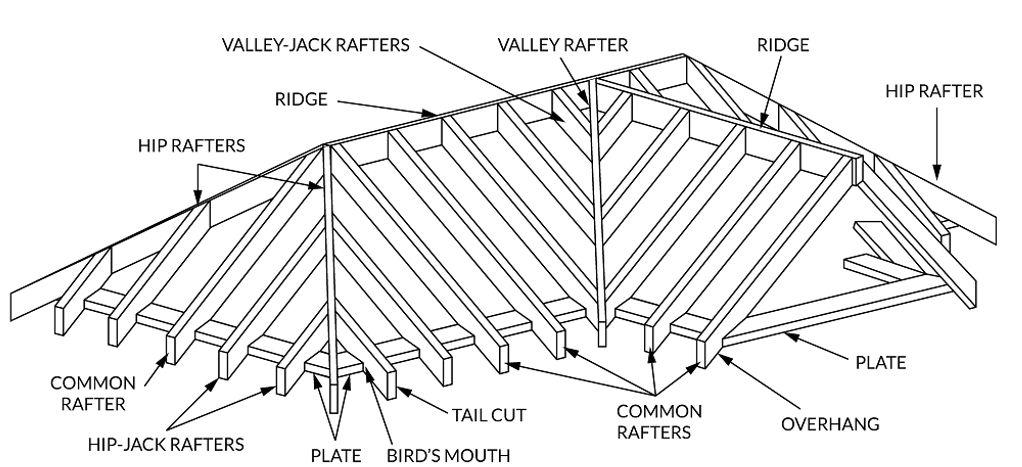
Roof Framing Components
Ridge boards
Ridge boards serve as the central component where the roof rafters from either side of the roof slope converge. They must have a thickness of at least 1 inch and an adequate depth that allows a secure attachment of the rafters with an extra margin of 2 inches, as shown in the below image. Connection of rafters to the ridge board by direct nailing is prohibited; instead, a gusset plate should be utilized for attachment.

Ridge Boards
Ridge boards serve as the point of connection for perpendicular roof frames. This meeting of frames creates a valley if the corner points inward (toward the house), and a hip when pointing outward. Valley or hip rafters, which run from the corner to the ridge board, are necessary in these instances. These rafters should have a minimum thickness of 2 inches and adequate depth to accommodate the cut end of other rafters. Given the substantial load they often bear, valley rafters are typically doubled, although not mandatory. For a typical house layout, a rafter of 2x10 or 3x8 inches should suffice. Doubling rafters provides more nailing space in challenging sections.
Rafters
Rafters, the main structural elements of a roof, typically measure 2x8 inches, but can range from 2x4 to 2x12 inches. The slope of the roof and the spacing of the rafters largely determine their size as these factors dictate the roof's span. When a valley or hip is present, the rafters, known as jack rafters, connect ridge boards (in valleys) or the hip rafter to the external wall.
Purlins
Purlins are horizontal beams used to support the weight of roof coverings. They also reduce rafter spans, enabling the use of smaller rafters in larger spans, as shown in the below image. Purlins should match the dimensions of the rafters they support, extend continuously from one end to the other, and be bolstered by 2x4 inch braces set 4 feet apart on center. These braces should be attached to an interior load-bearing wall at an angle of at least 45 degrees from the horizontal surface. For braces longer than 6 feet, 4x4 inch braces should be used, spaced 4 feet apart on center and not exceeding 8 feet in length.
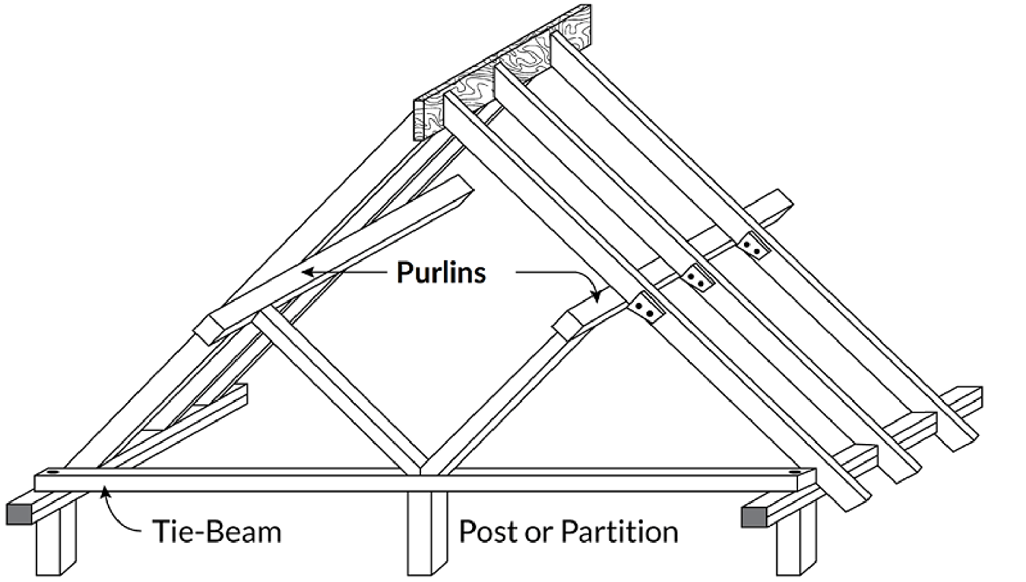
Purlins
Ceiling Joist, Rafter and Collar Ties
Ceiling joists, also known as rafter ties, are integral components of roof framing. Typically, these joists come in sizes like 2x6, 2x8, or 2x10 inches. They are installed at points where rafters intersect with partition walls, and are securely fastened to both the walls and the ends of the rafters using 16d common nails. Ceiling joists should span continuously from one end to another and be securely fastened where they meet the internal load bearing walls. The ends of these joists can either butt against the external walls or overlap by a minimum of 3 inches, using the toe nailing technique.
In cases where it's not possible to connect ceiling joists to rafters at the intersection with the wall, joists may be positioned higher within the roof frame to act as rafter ties. This is acceptable without requiring engineering if the span between bearing walls is less than 25 feet. If joists run perpendicular to rafters, rafter ties with a minimum size of 2x4 inches should be installed using appropriate metal connectors.
Lastly, collar ties are included in roof framing when there's an expectation of high wind uplift forces. Collar ties must have a minimum nominal size of 1x4 inches, with a maximum spacing of 4 feet on center, and should be situated in the upper third of the roof framing.
Rafter and collar ties
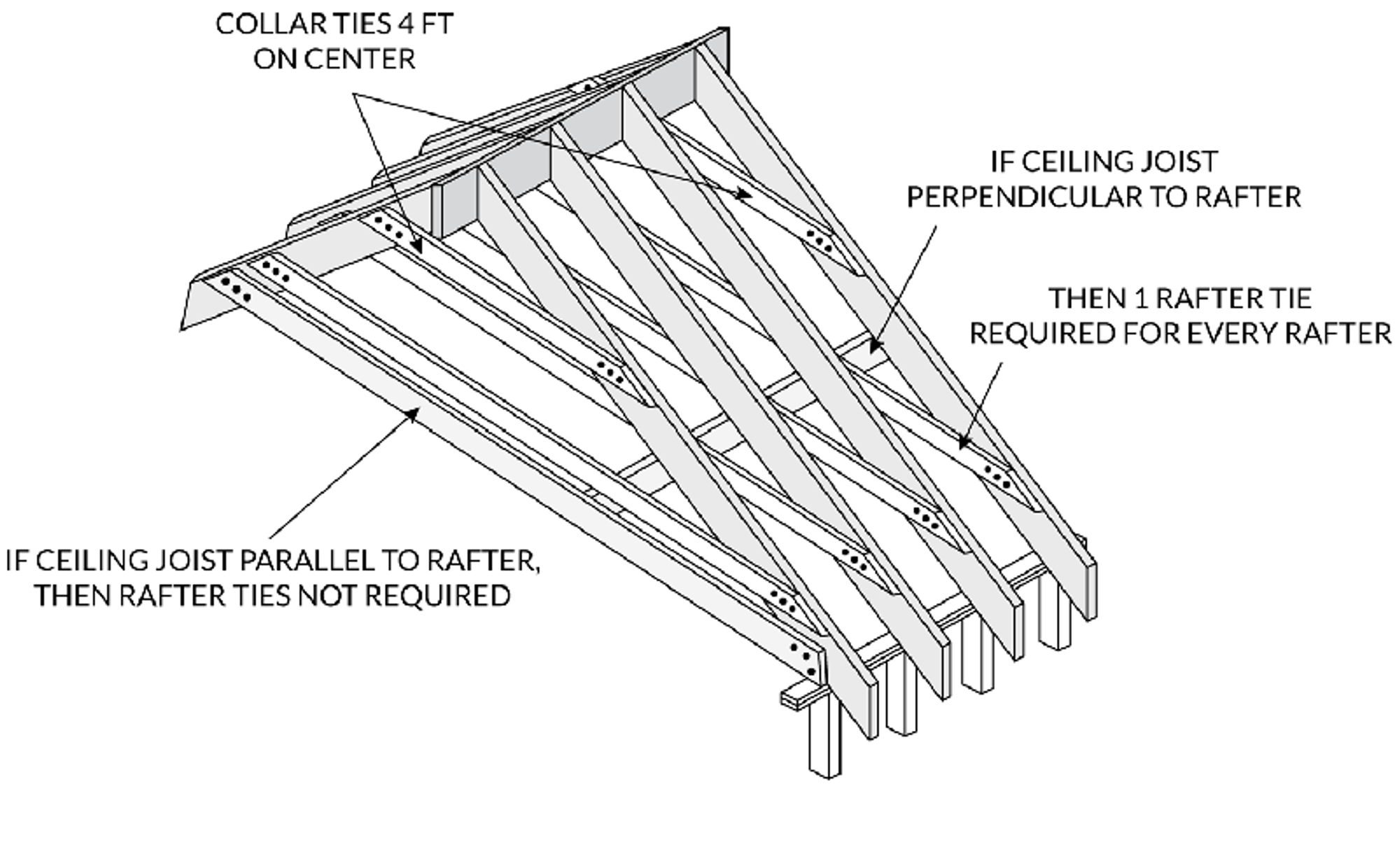
Rafter and collar ties
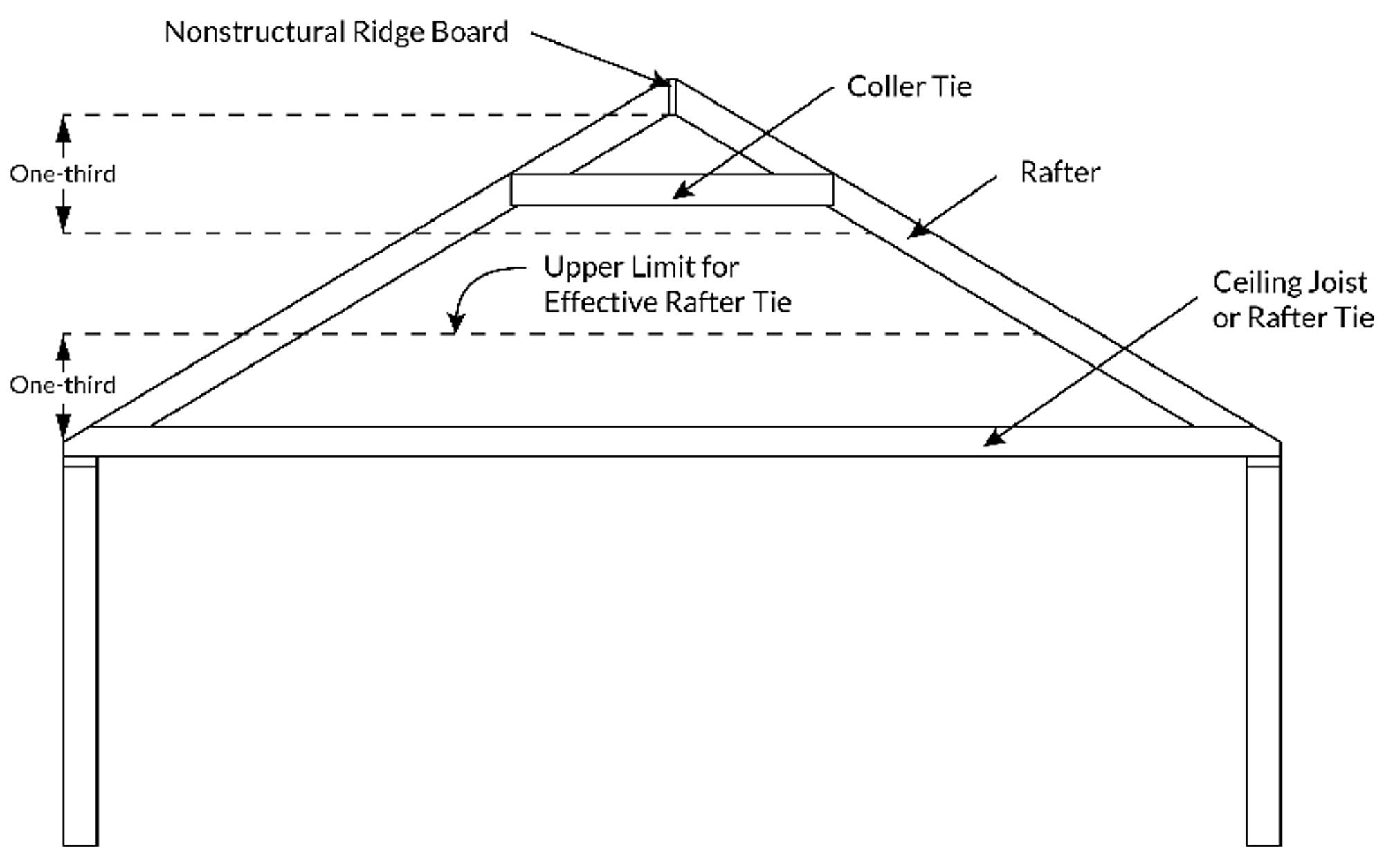
Roofing/Construction Square
A roofing or construction square is a unit of area commonly used in roofing and equals 100 square feet (10x10 feet). This unit is often used by suppliers to price their roofing materials. For instance, if you have a roof that covers an area of 1200 square feet, you would need to purchase 12 roofing squares (1200 sq ft divided by 100 sq ft per roofing square).
Measuring Rafters
In order to determine the length of a rafter when you know the rise and the run, you would calculate the hypotenuse. For example, using the below image as a guide, if the rise is 5 feet and the run is 10 feet, you would calculate the length of the rafter, including an additional 2 feet for eave overhang, as follows.
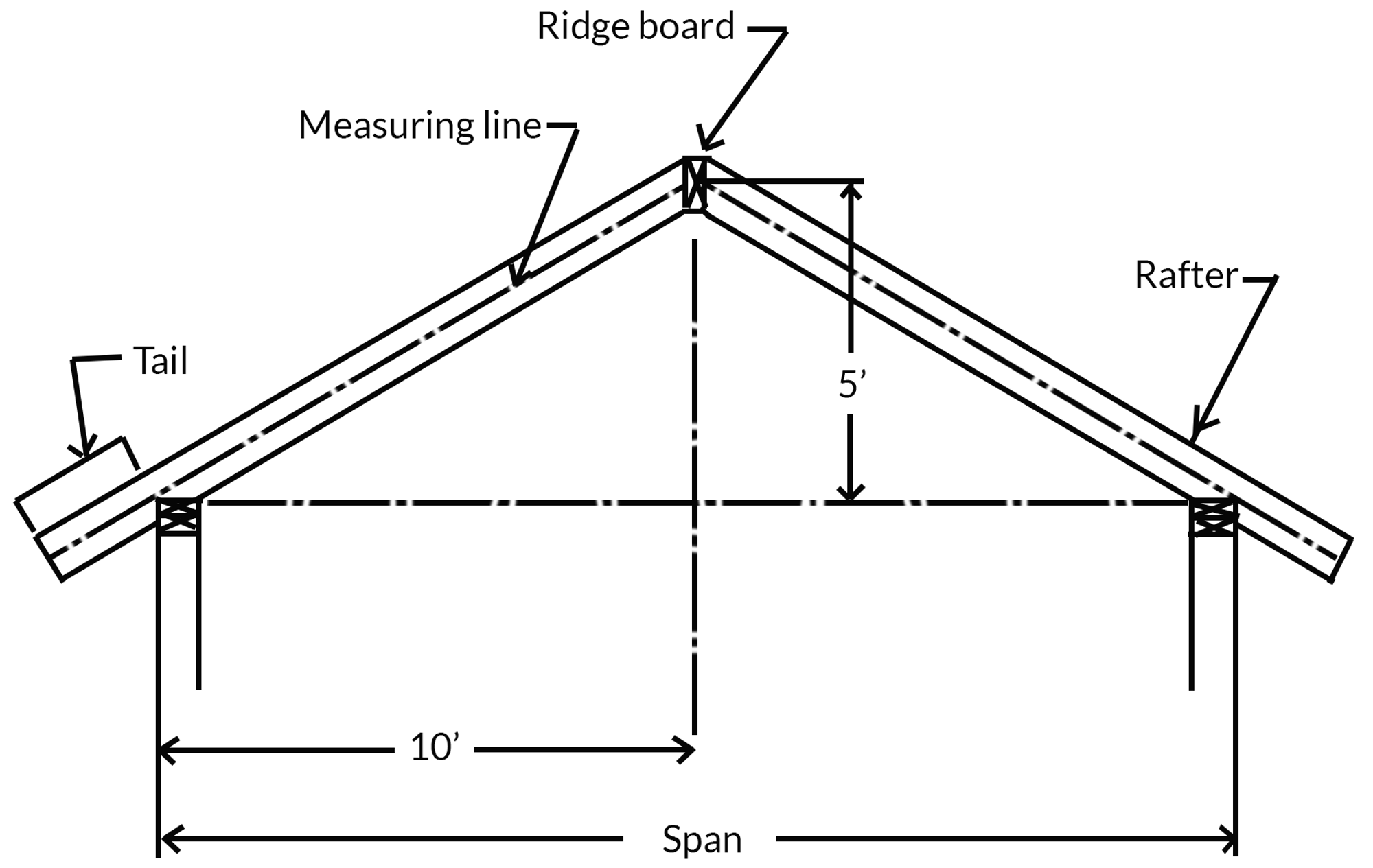
Roof Calculation Example
To calculate the rafter length, begin by identifying the length from the center of the ridge board (measurement line) to the tail (eave overhang). Utilize the following formula to compute the hypotenuse:
A2 + B2 = C2
52 + 102 = C2
25 + 100 = C2
√125 = √C2
11.18’ = C
This means that the length from the peak of the ridge to the start of the eave overhang is 11.18 feet. Adding the extra 2 feet for the eave overhang gives a total rafter length, including the eave overhang, of 13.18 feet.
If the query requires the cumulative length of both sides of the rafters, simply double the calculated length:
13.18 × 2 = 26.36 feet
Pitch versus Slope
This segment discusses the distinction between pitch and slope. the below image illustrates the relationship among rise, run, and span. Run refers to the measurement of the right triangle’s base. Span measures the total distance from one side of the gable to the other. Rise is a measurement from the bottom of the gable to the middle of the ridge board.
Rise, Run, and Span
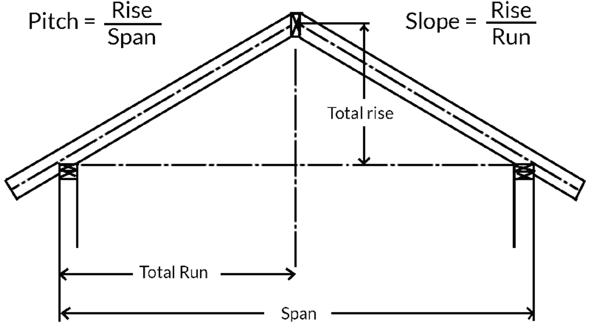
The calculation of pitch involves dividing the rise by the span. However, to calculate slope, you divide the rise by the run. The roof needs to be symmetrical to have a pitch. If it's not symmetrical, instead of having a pitch, the roof will have two different slopes.
Given the following values from the below diagram:
Rise = 4’
Run = 12’
Span = 24’
We can calculate:
- The slope (rise divided by run) as 4/12 (expressed as 4:12).
- The pitch (rise divided by span) as 4/24 or simplified to 1/6
The slope is typically presented with a denominator of 12. Therefore, if the rise is 2 feet and the run is 6 feet, the answer would be 4/12 or indicated as 4:12.
The pitch, on the other hand, is typically reduced to its lowest common denominator. So, if the rise is 2 feet and the span is 12 feet, then the pitch would be 1/6.
Bear in mind that some questions on the state exam could be compound calculations. Therefore, simply knowing the formula to find the hypotenuse might not be enough. Furthermore, the state exam might not always ask you to calculate the pitch and slope. Instead, it might provide the pitch or slope and ask you to calculate a missing dimension, as shown in the below image.
Recalculated Example
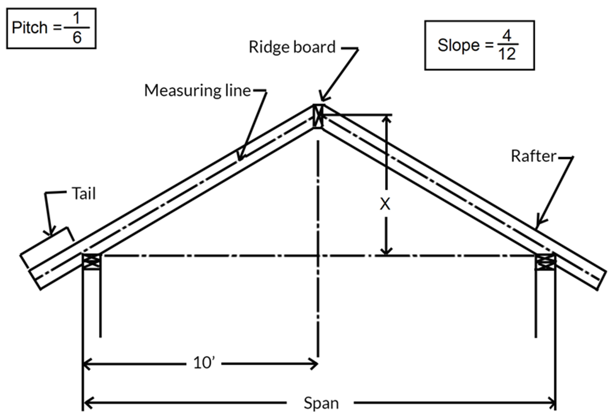
Slope Calculation
As depicted in above image, the run is set at 10 feet while the rise is unknown, hence it's marked as “X”. The challenge here is to calculate the rise, given a slope of 4:12 and a run of 10 feet.
The slope is represented with a denominator of 12, so in a 4:12 slope, there will be a rise of 4 inches for every 12 inches (1 foot) of run. Now, if there is a 4-inch rise for every 12 inches (1 foot) of run, then what would be the total rise if the run is 10 feet? Multiplying the 4-inch rise by the 10 feet of run gives us a total rise of 40 inches. Thus, X equals 40 inches or 3 feet 4 inches.
Pitch Calculation
On the other hand, the question might present the pitch instead of the slope, necessitating additional steps to determine the value of “X”. In the above images, a roof with a pitch of 1:6 is illustrated, indicating that for every 6 units of span, there is a rise of one unit. Even though the preceding problem doesn't specify the span, it can be easily calculated by doubling the run. Hence, if the run is 10 feet, the span would be 20 feet.
The subsequent step involves multiplying the span by the numerator of the pitch and dividing it by the denominator. For instance, by multiplying 20’ by 1 (the numerator of a 1:6 pitch) and then dividing by 6 (the denominator), we get a result of 3 feet 4 inches.
When the problem is solved using both slope and pitch, the solution remains the same, as a pitch of 1/6 and a slope of 4/12 are equivalent. However, the slope relates to the run, while the pitch pertains to the span.
Gutter Estimation
Gutter estimation can pose a challenge for individuals who have never undertaken gutter installation before. While a prudent contractor would order additional material to account for small mistakes, the state exam necessitates a precise answer and does not account for waste. Gutters are quantified in linear feet. It's crucial to remember that measurements should be taken along the longest possible line. The below image provides an example of how to measure gutters using a gutter diagram.
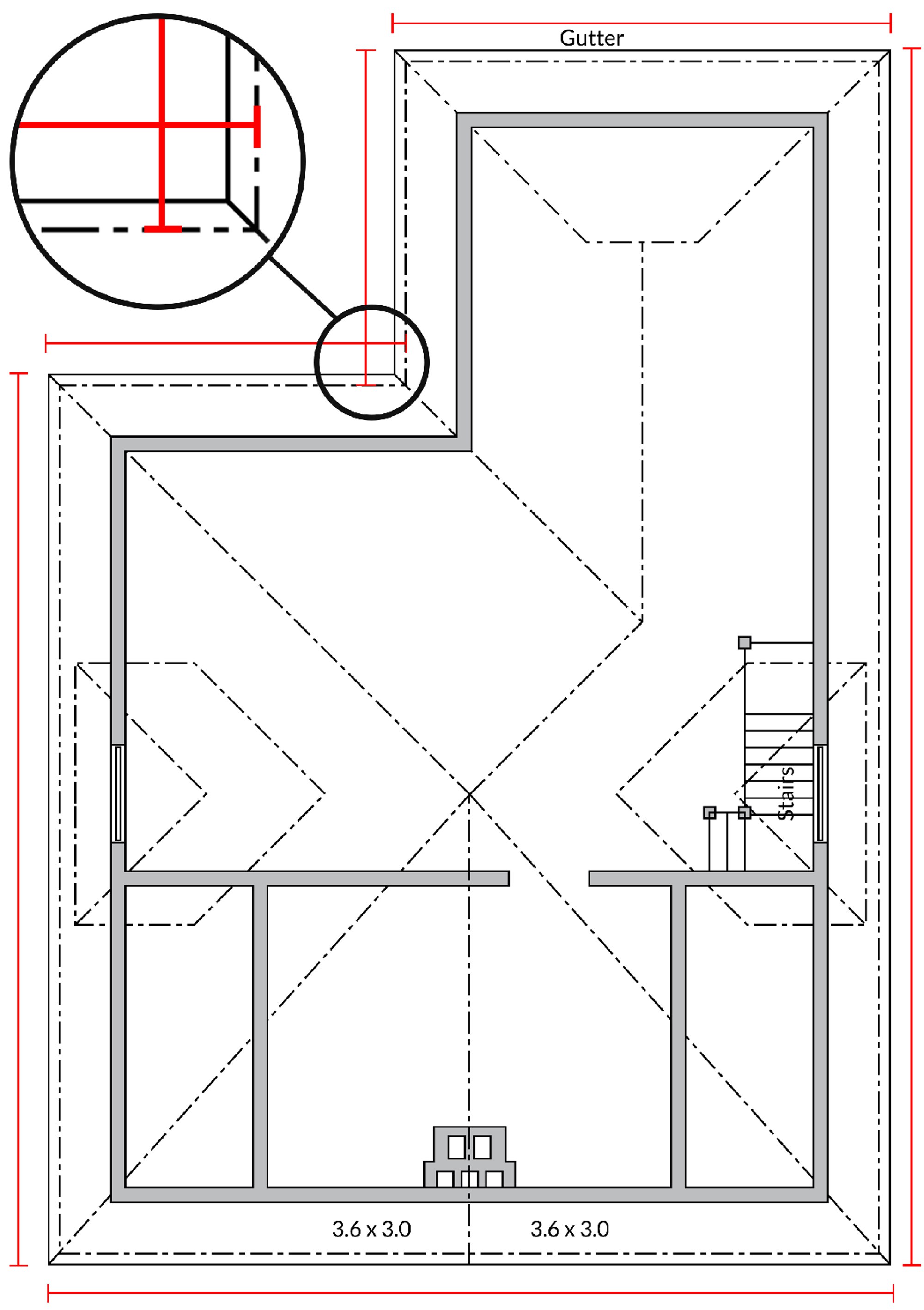
Common Types of Roofs
Roofs serve a dual purpose. Firstly, they shield the structure from environmental elements, requiring minimal upkeep while enduring wind and snow loads. Secondly, the choice of roofing style is a key factor in complementing the architectural aesthetics of a building. The below image illustrates the most frequently used residential roofing styles, which include gable, hip, flat, and shed.
Roof types
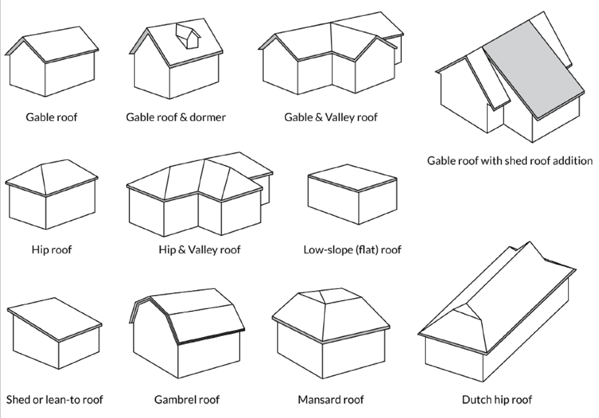
Gable Roof - This is the most prevalent type of roof found in homes. It features two sides that slope and intersect at the top, forming a gable, or a triangular wall covered by the roof, at both ends. If a gable roof has a dormer, it will include a window for ventilation and light.
Hip Roof - This type of roof has sides that slope on every side of the building. There are no gables on a hip roof, which means it requires less maintenance. It is more robust and can withstand severe weather, making it ideal for areas prone to harsh storms.
Shed Roof - Also known as a lean-to roof, this design slopes in one direction only. It is often employed when adding to an existing structure. As illustrated in the image , this roof can be attached to the side of the structure.
Gambrel Roof - This is a symmetrical roof with two slopes on each side. The upper slope has a shallow angle, while the lower slope is steeper. This design combines the advantages of a sloped roof with the benefit of maximizing headroom in the building's upper level and reducing the height of what would otherwise be a tall roof.
Low-Slope Roof - Often referred to as a flat roof, it is not entirely flat. The rafters have a slight incline to form a slope that allows for water drainage.
The roof's slope is influenced by factors like drainage, design, attic volume, and roof pricing. Typically, the steeper the roof's slope, the more challenging the installation due to regulations that set 8:12 as the maximum workable slope. For extremely steep slopes, additional fasteners are required. On the other hand, slopes of 1:12 or 2:12, often considered Flat Roofs, are less desirable due to issues with leakage, ventilation, and ergonomics.
The term Steep Roof lacks a precise definition as contractors' interpretations of what constitutes a steep slope vary. Generally, any slope from 4:12 to 21:12 necessitates the use of "steep sloped materials" for sheathing. Roofs with a 21:12 slope, known as Mansard Roofs, require additional fastening methods as per the manufacturer's installation instructions, even though these methods are not specified in the Building Code.
Advantages of Steep Roofs include:
- Long-lasting sheathing material due to higher slopes;
- Increased attic volume;
- Appealing design;
- Efficient water drainage.
Ventilation
Ventilation in the roof is crucial to prevent condensation during colder weather and heat buildup during warmer periods. The vent opening should be a minimum of 1/16 inch wide, but should not exceed 1/4 inch. These vents should be designed to withstand environmental factors, such as corrosion. The minimum ventilated opening should be a 1/150 fraction of the net roof area. This translates to 1 square foot of vent for every 150 square feet of net roof area. This ratio can be reduced to 1/300 if specific criteria such as the use of vapor retarders or ventilators are met.
A single louver-style vent that satisfies the 1/150 rule is generally adequate for gable roofs. For hip roofs, vents are installed at the eave soffits and additional ventilators are added to ensure proper ventilation. If eave vents are used, insulation must be installed in such a way that it doesn't obstruct free airflow, maintaining a 1 inch gap between the roof sheathing and the insulation in that area. The California Building Code allows for unvented roofs or attics, provided several specific requirements are met.
Connectors
Roof framing typically utilizes three types of connectors: the rafter to ridge board connector required by the California Building Code; the variable pitch connector (VPA) used for connecting elements with varying slopes; and the lateral truss/rafter to double plate connector.
Designs for the rafter to ridge board connector vary among manufacturers. It typically consists of a thin plate positioned above the ridge, welded to a larger plate at a right angle that supports the rafter, as depicted in below image.
Ridge Rafter Connector
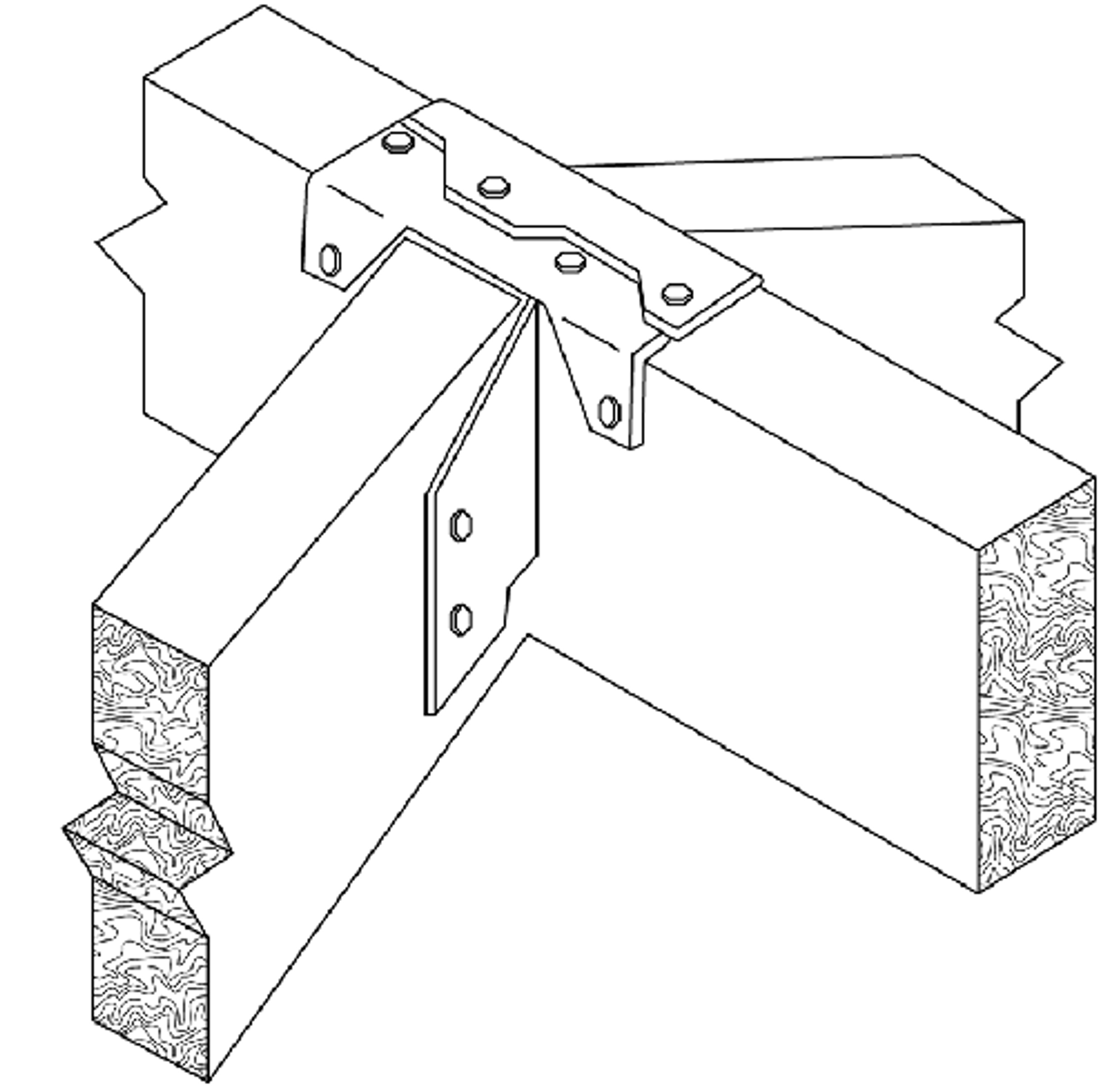
The VPA facilitates the attachment of rafters to the top wall plates without requiring a birdsmouth. Its main function is to ensure a sturdy linkage between elements with varying slopes, as depicted in the below image.
VPA Connector
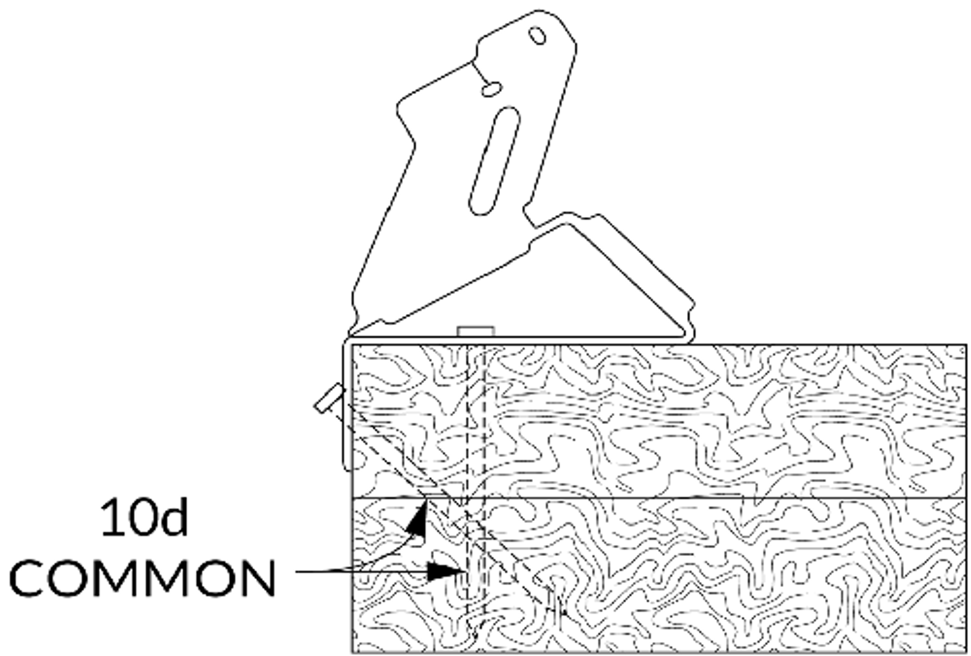
The use of connectors for lateral truss/rafters to double plate is quite prevalent in areas prone to high winds. The reason behind this is the enhanced stability offered by these connectors, as shown in the below image.
Lateral truss/ Rafter Connector
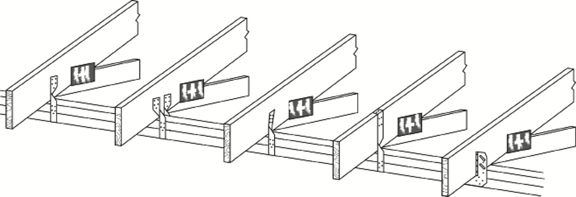
Notching, Cutting and Drilling Requirements
In rafters, notches should remain under 16% or 1/6 of the rafter's depth, and they should not exceed one-third of the rafter's depth. Notches should not be placed in the middle third of the span. As for holes, their diameter should not be more than one-third of the depth of the rafter and they should be positioned at least 2 inches away from the top and bottom of the member and from any adjacent notch.
A "birdsmouth" is a triangular notch created on the bottom of the rafters to enhance the bearing value between rafters and walls. The birdsmouth is formed by making a horizontal "seat cut" that is the same length as the width of the wall plate, and a vertical "heel cut" that is 1/6 of the rafter's depth. Refer to the below image.
Birdsmouth
